The "EL84 Engineer's Amplifier" - a smaller, simpler, easier engineer's amp
(It's sort of a long story)
(Note that the photos are hyperlinked to full-size photos in grisly detail)
The PCB is now available on eBay!
This project was born out of a shootout at ETF.24 (European Triode Festival). The shootout was to design and build an amplifier, given a fixed set of parts, in 2-3 days. I joined a US team consisting of John Bollinger and two remote members in the US, Jeremy Epstein and Douglas Piccard. The parts "kit" included EL84 output tubes and a push-pull OPT, as well as a power transformer and an assortment of other driver tubes and parts.
Many years ago Douglas and I were both working on an amp topology that used the ultralinear tap of an OPT to provide feedback to the driver stage. He coined the term 'E-linear" for this. You can see a SE amp I designed using this concept here: E-linear amplifier. For the ETF amp, we thought that something using some sort of similar topology would be cool.
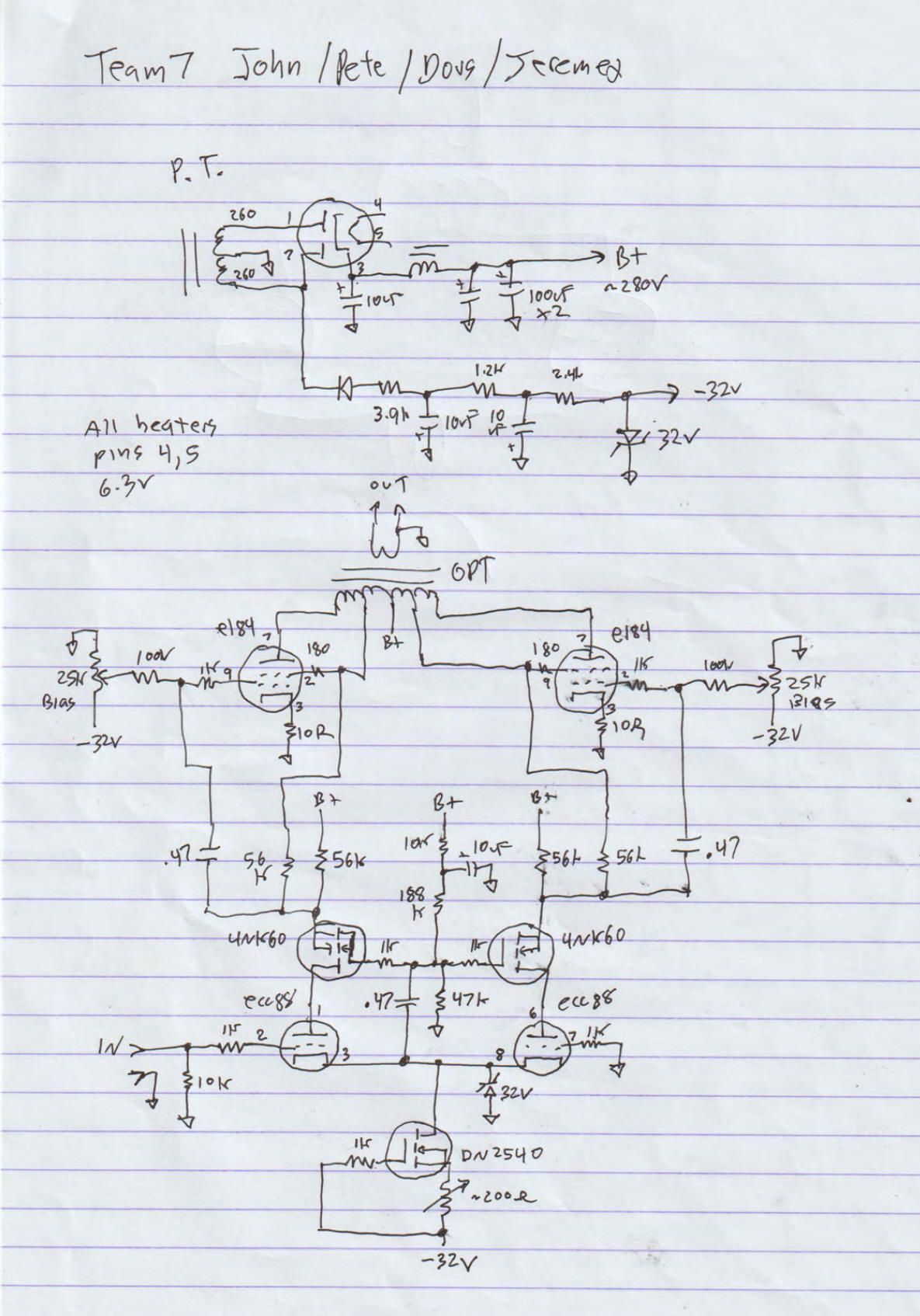
Douglas came up with the circuit: an ECC88 cascode with N-channel MOSFETs in a differential amp circuit, driving a pair of EL84s, with E-linear feedback to the driver. This is what we came up with:
Building it was a challenge. We were given a kit containging the major parts...
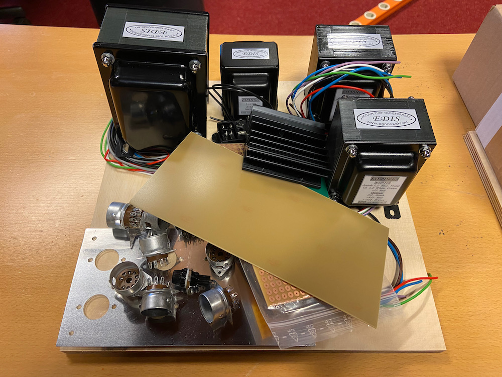
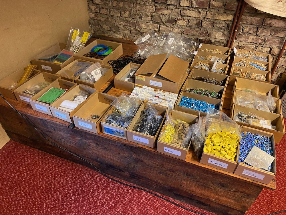
...and access to an assortment of other parts:
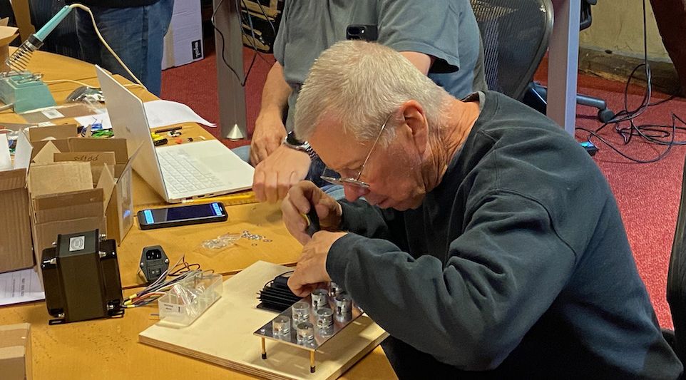
We did OK, considering that we didn't bring any tools or equipment, and relied on begging and borrowing... here is John starting assembly;
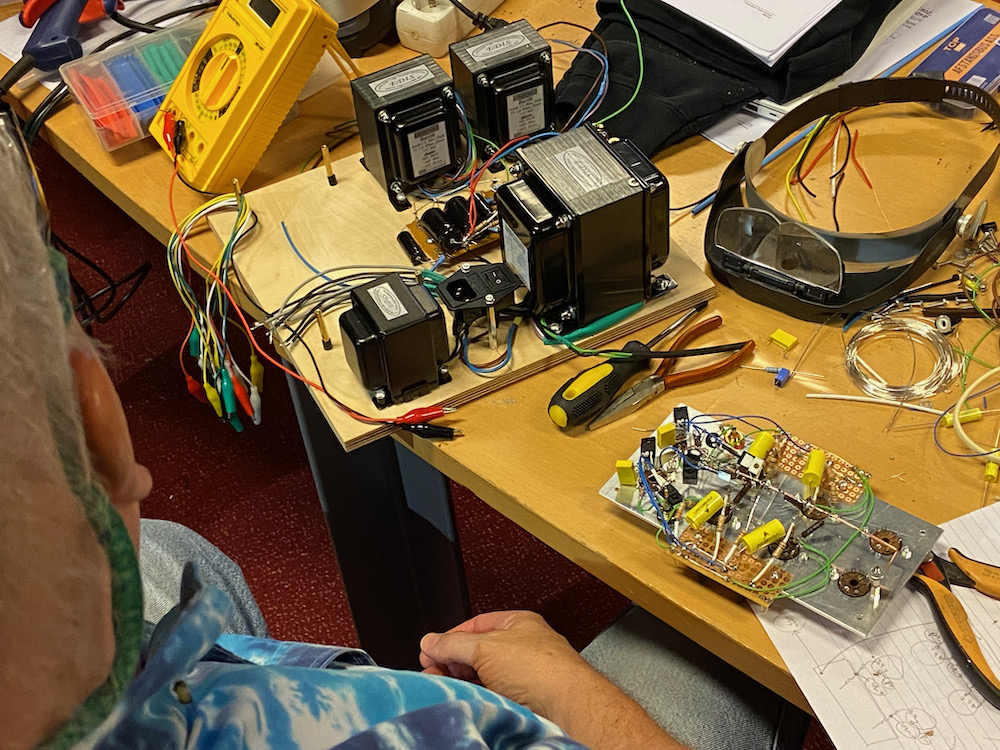
You can see it's sort of a rats nest. (Looking over my shoulder).
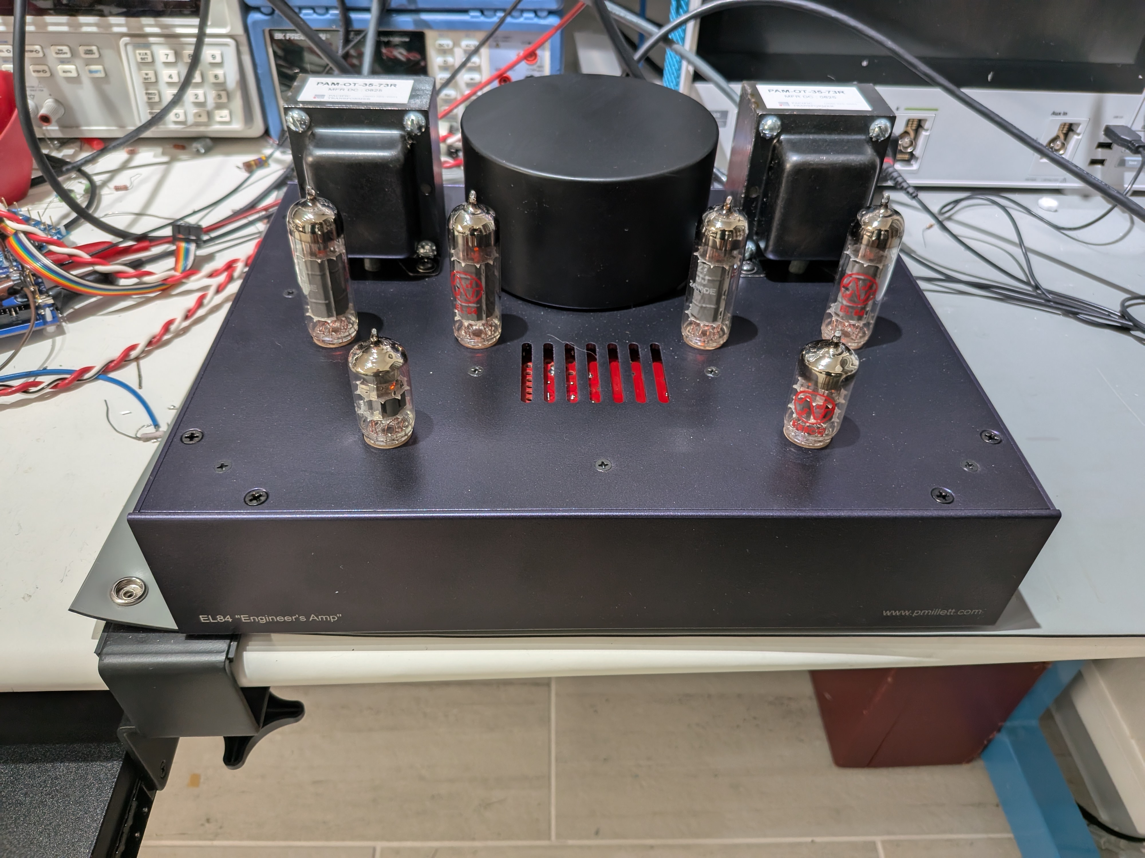
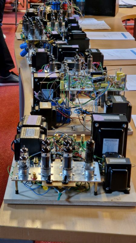
Here is our finished amp:
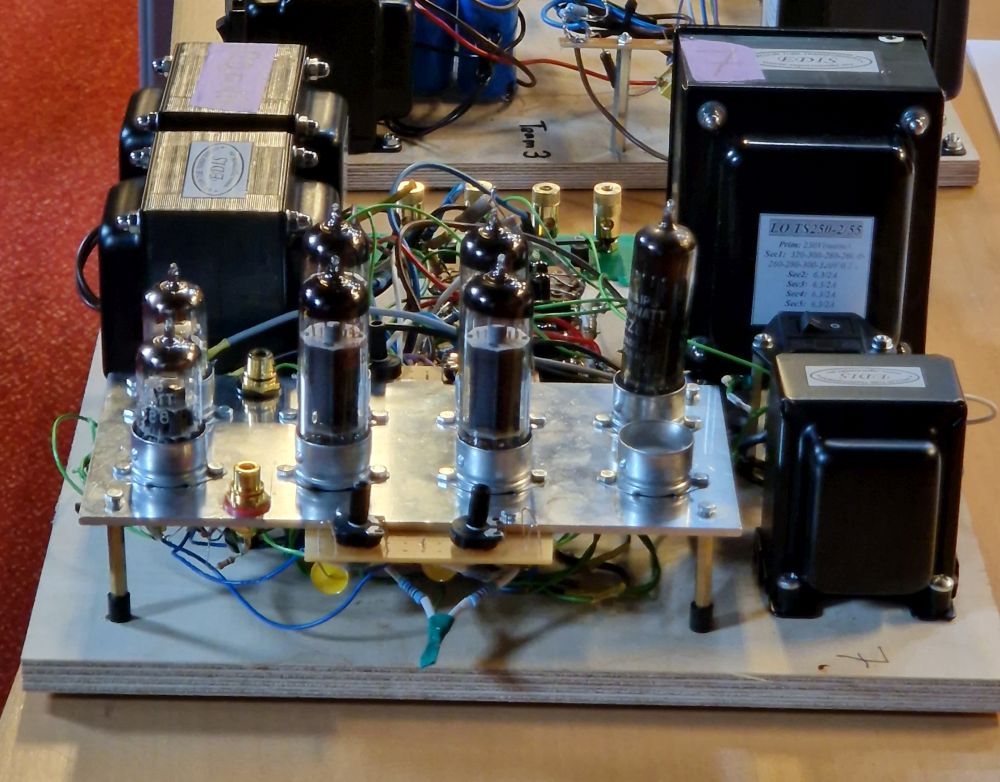
one of many...
Unfortunately, in the listening tests... it sounded nasty. There was clearly something wrong. Since we didn't bring any test equipment to ETF - our signal source was John's iPhone, and we borrowed a DMM to measure gain - we didn't really have a chance to measure it or do any critical listening. I'm not sure what the problem was, likely either a wiring mistake or a wrong component somewhere, or it was oscillating.
Fast forward a couple of months and I decided I wanted to understand why this didn't work as it should have. I did some LTSpice sims (you can download the LTSpice file for the entire design below) that showed that it should have worked just fine. So I made a version of the circuit on a PCB for testing:
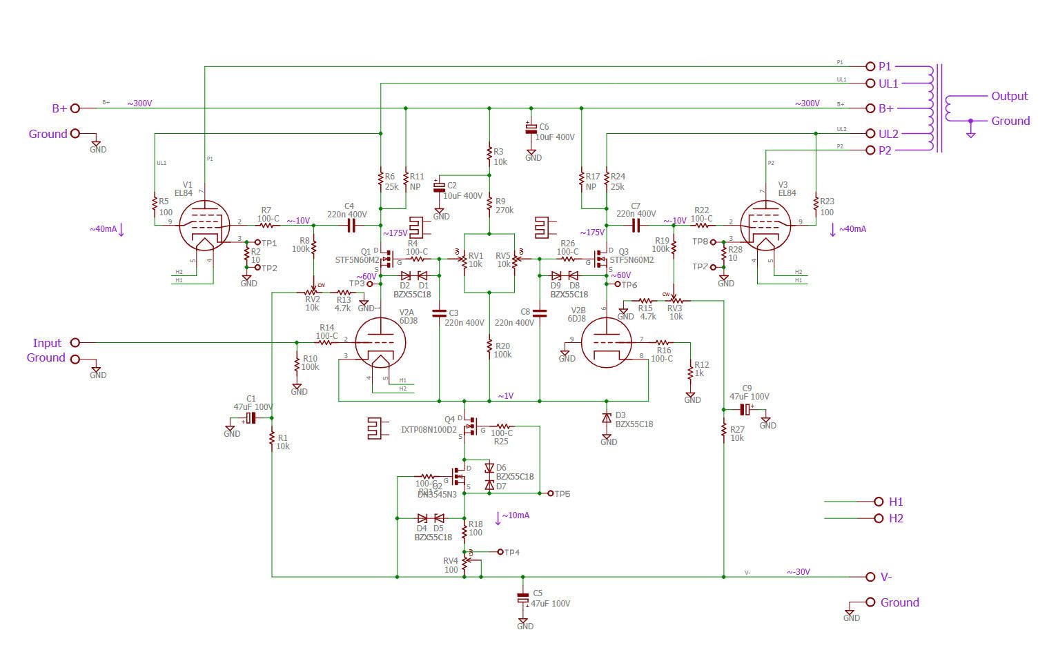
More or less the same as the ETF amp. But this circuit worked pretty well, after I tamed some oscillation by adding some compensation caps across the resistors connected to the ultralinear taps.
After tweaking the circuit a bit - and adding global feedback - I was really impressed with its performance. So I decided to morph this into a stereo amp project, similar to the "Engineer's Amp" stuff that I did previously. My goals were to make it as simple as possible - no crazy boutique parts, no adjustments needed, and simple to assemble.
Design
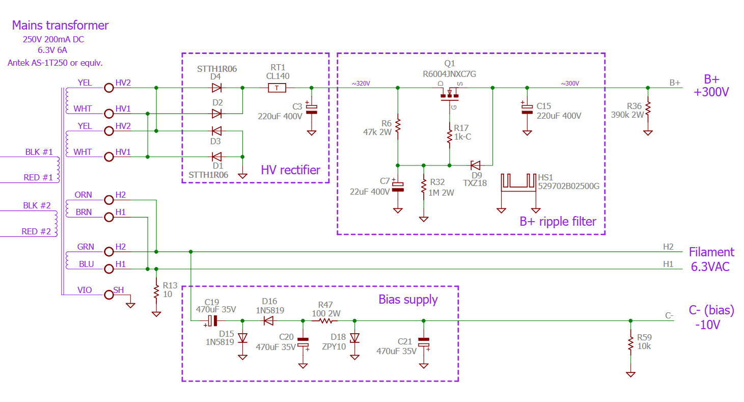
Download the full schematic (PDF)
Download an LTSpice simulation (zipped .ASC file)
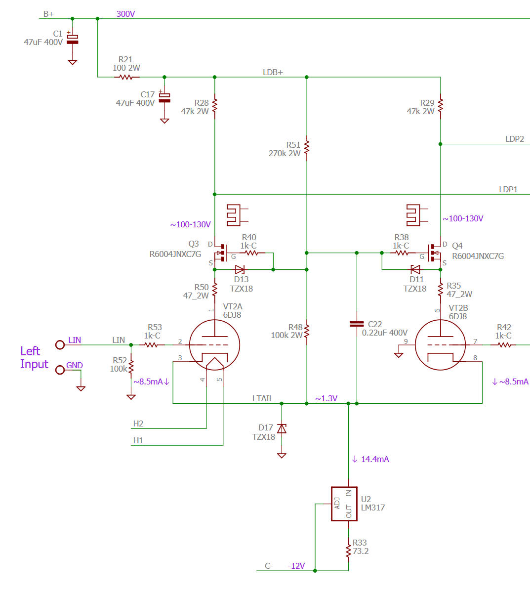
The input is still the cascode diff amp, but now I am using the inverting input for global feedback. To meet the "no adjustments" requirement, I changed to a simple LM317 current sink (cascode MOSFETs really need individual adjustment) and added a touch of degeneration in the source terminal of the MOSFETs (that 47 ohm resistor). That improved the balance between sections.
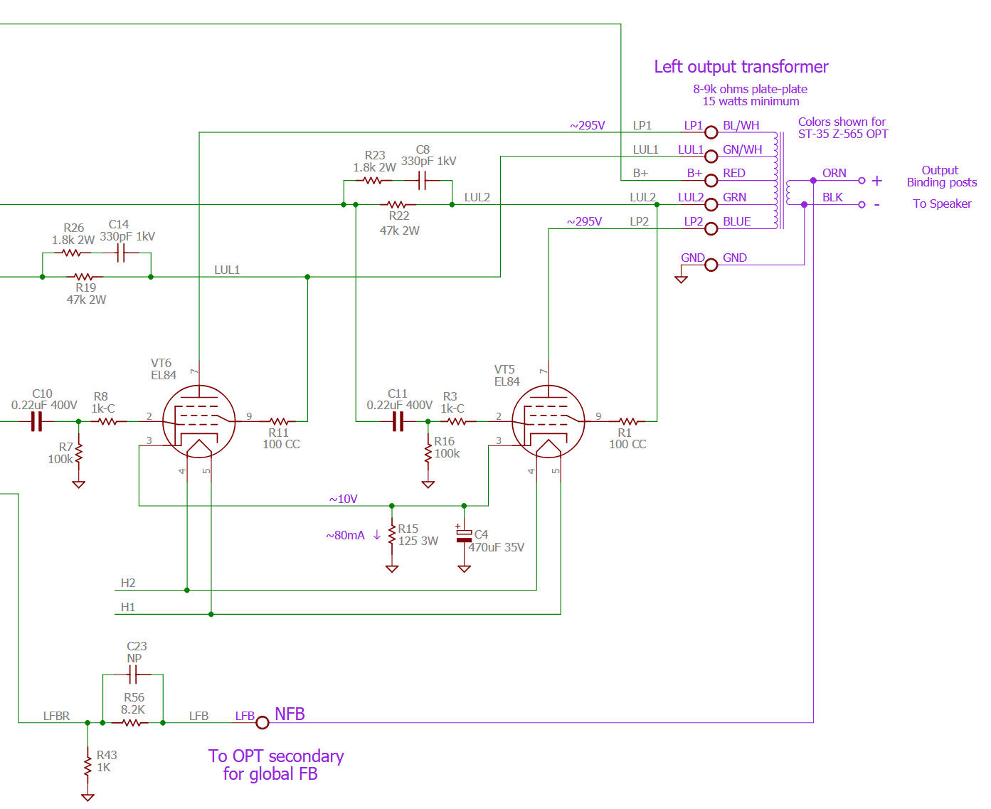
The output is straightforward. Note the compensation network (RC) across the ultralinear resistors. Also note I also added resistors from the drain of the cascode MOSFETs directly to B+. I did this to increase the gain a bit (since I am adding loop feedback) and it also seemed to improve stability. To meet the "no adjustments" requirement, it uses cathode bias instead of fixed bias. I set it fairly conservatively at 40mA per tube (11 watts plate plus screen), so the output power is around 14 watts.
The power supply is modeled after the original Engineer's Amp, using a cheap MOSFET ripple filter instead of a (expensive and heavy) choke. One oddity here is that I used a voltage doubler off of the filament supply to generate a negative rail (-10V) to bias the tail CCS for the driver. I wanted to use an inexpensive, off the shelf power transformer. I found an Antek toroid that was perfect, but no bias winding - so this worked well, though it also means that the heaters have to be referenced to ground (no biasing it up).
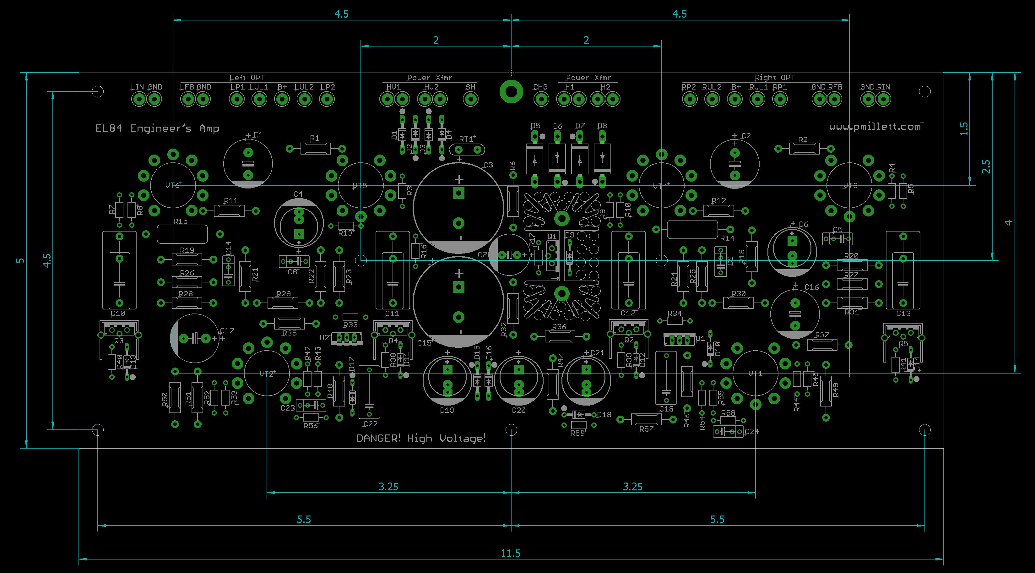
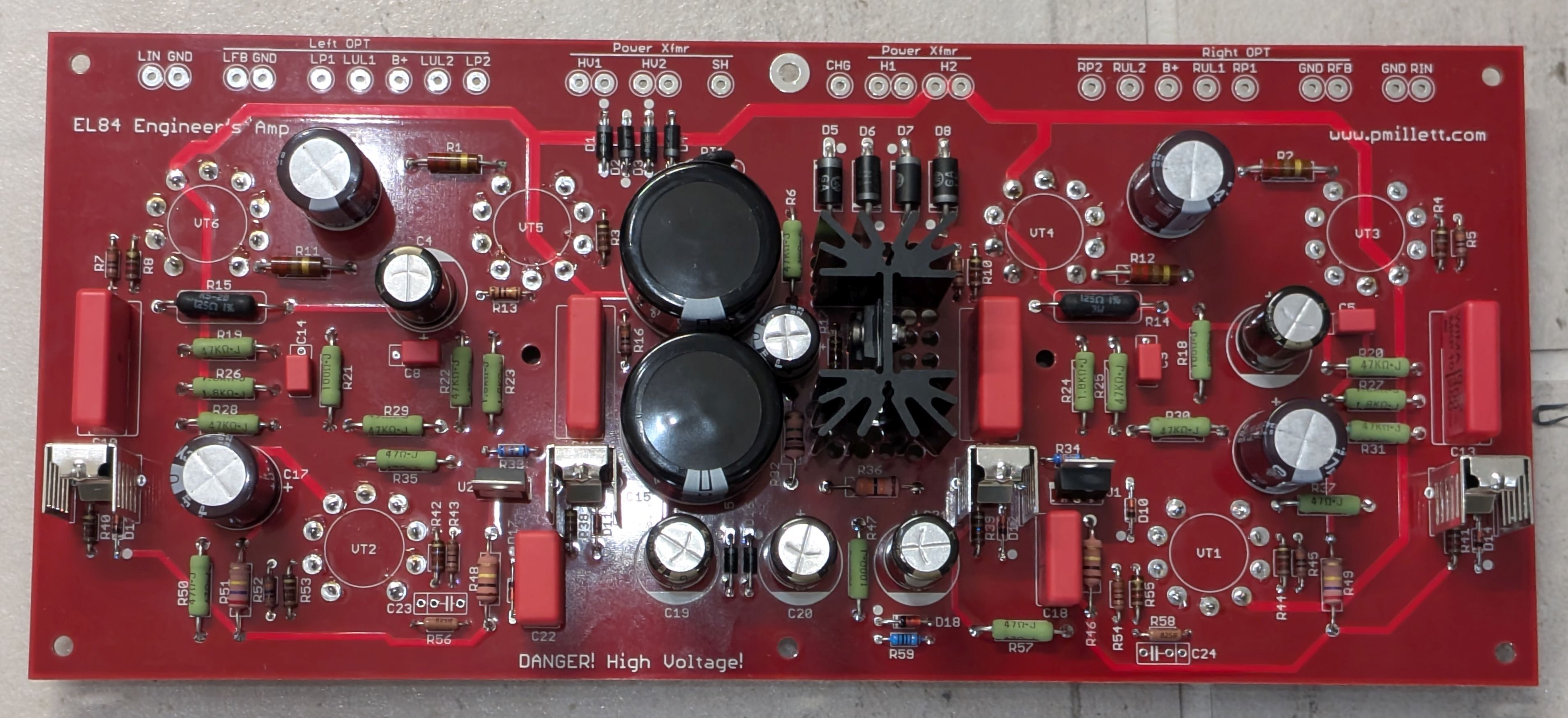
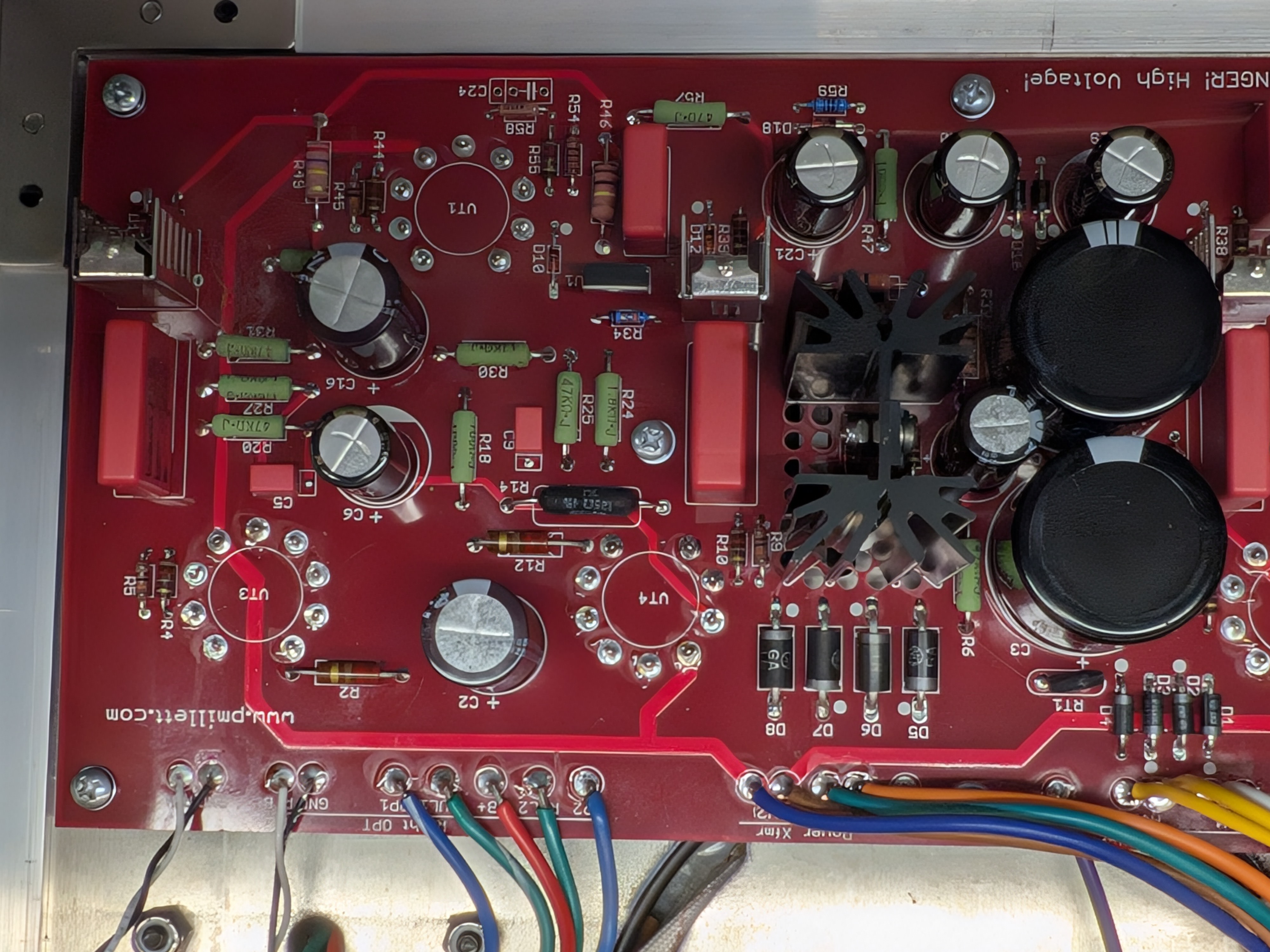
Here is what the PCB came out like (click images for full size JPG or PDF files):
Components
Most of the parts can be obtained from a disti like Mouser or DigiKey - refer to the parts list. Download the full parts list (BOM) in PDF or XLS format.
The PCB is now available on eBay: https://www.ebay.com/itm/167686850222
One part that people always have issues with is carbon comp resistors, which I usually use for grid stoppers. Yes, you can use other resistor types if you want. But there are still plenty of carbon comps to be found in the surplus market for reasonable prices. Grid stoppers don't have to be any particular exact value - use something other than 1k or 100 ohms and you can find plenty of them. Refer to the BOM for a good source, Surplus Sales.
I tried a number of different output transformers with this circuit. I settled on Dynaco ST-35 clone OPTs. There are a couple of companies making them, and these performed better than the other off-the-shelf options I tried. One from Pacific Audio Magnetics performed slightly better than the one from Musical Power Supplies (datasheet), but both are perfectly acceptable, and the MPS transformers are less expensive. If you look at the square wave responses below you can see a little difference, though I optimized the compensation for the Pacific OPT, so it might be improved with the MPS OPT by tweaking the compensation. One thing I found, though, is that the polarity is different between the two. I had to flip the output winding of the MPS OPT. I don't know which one is right, since I don't have am original Dynaco OPT. No big deal, if you power up the amp and it oscillates, flip a winding.
Note that these OPTs have a 25% ultralinear winding, not the usual 40%. 40% will work, though you might need to tweak the cascode load resistors to get a bit less from the UL tap and a bit more from B+.
As I mentioned, power comes from an Antek AS-1T250 toroid. Very reasonably priced and provides the correct voltage needed. I also used thier fancy round enclosure to make it pretty :)
I used JJ tubes. You can use whatever you want. I tried some ridiculously expensive Amperex ECC88 tubes and couldn't measure any difference.
Since there are no balance adjustments, it's best if you use matched pairs of EL84s in the output. Ideally, an ECC88 / 6DJ8 tube that is matched between sections is desirable. There are only a few people that will do that for you . You can ask Eurotubes to do it...
Construction
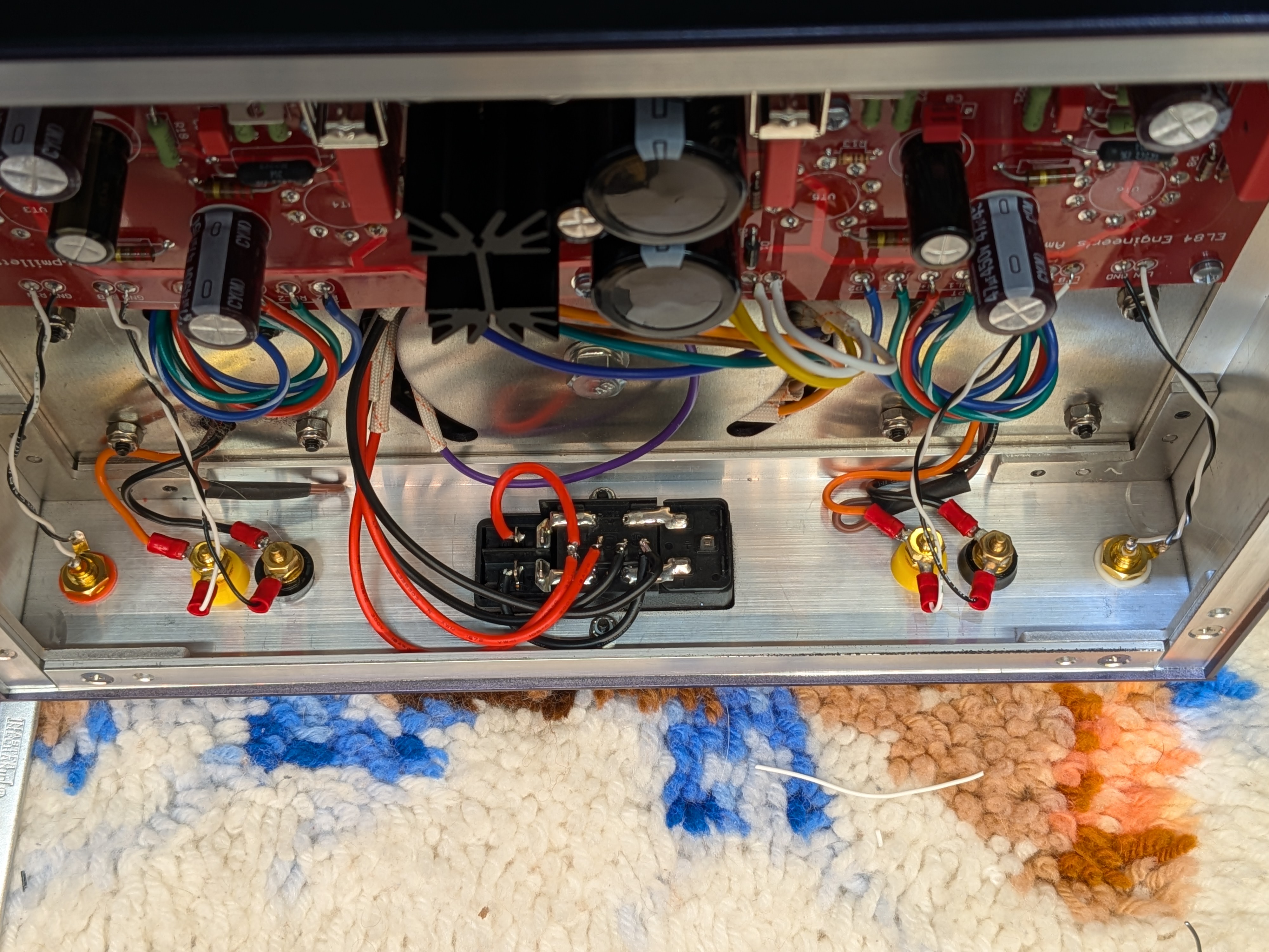
Construction is all on one PCB. The transformers wire directly to the board, as do the inputs.
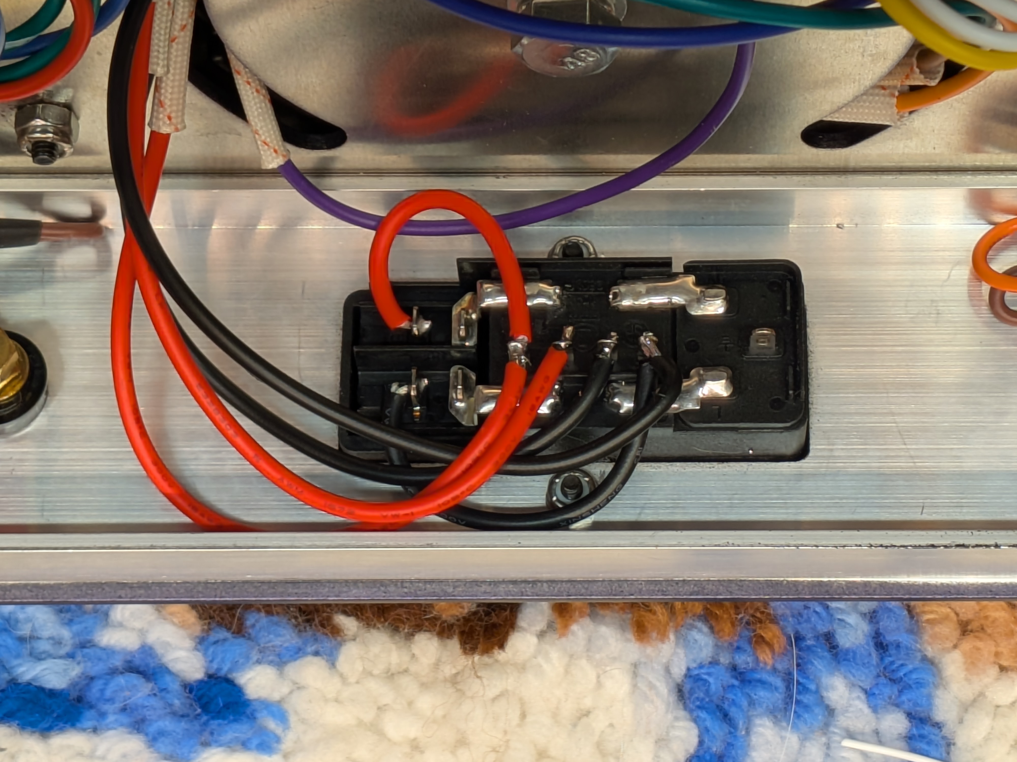
The power transformer primary is wired to an AC inlet module, which allows for 120V or 240V operation. BE CAREFUL doing this as there are 2 red and two black wires, and they are NOT interchangable. Refer to the schematic. The wires come out of the transformer in order, so the red and black for winding #1 are next to each other, then the red and black for winding #2. If in doubt use a DMM to verify continuity between wires.
I had Landfall Systems build the chassis for me. They can make you one too... or you can download the mechanical drawing and make one yourself (zipped AutoCAD R12 DXF)
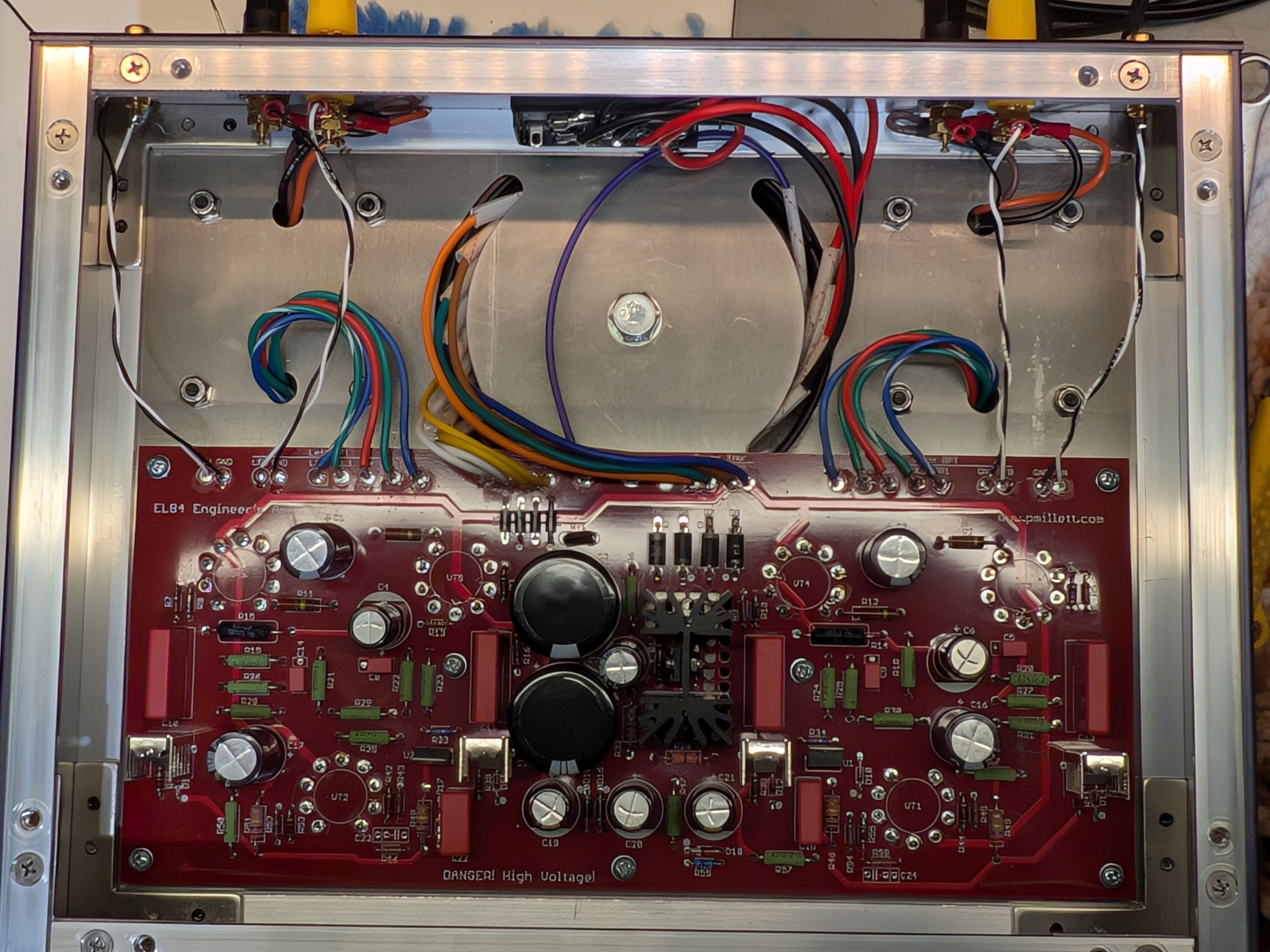
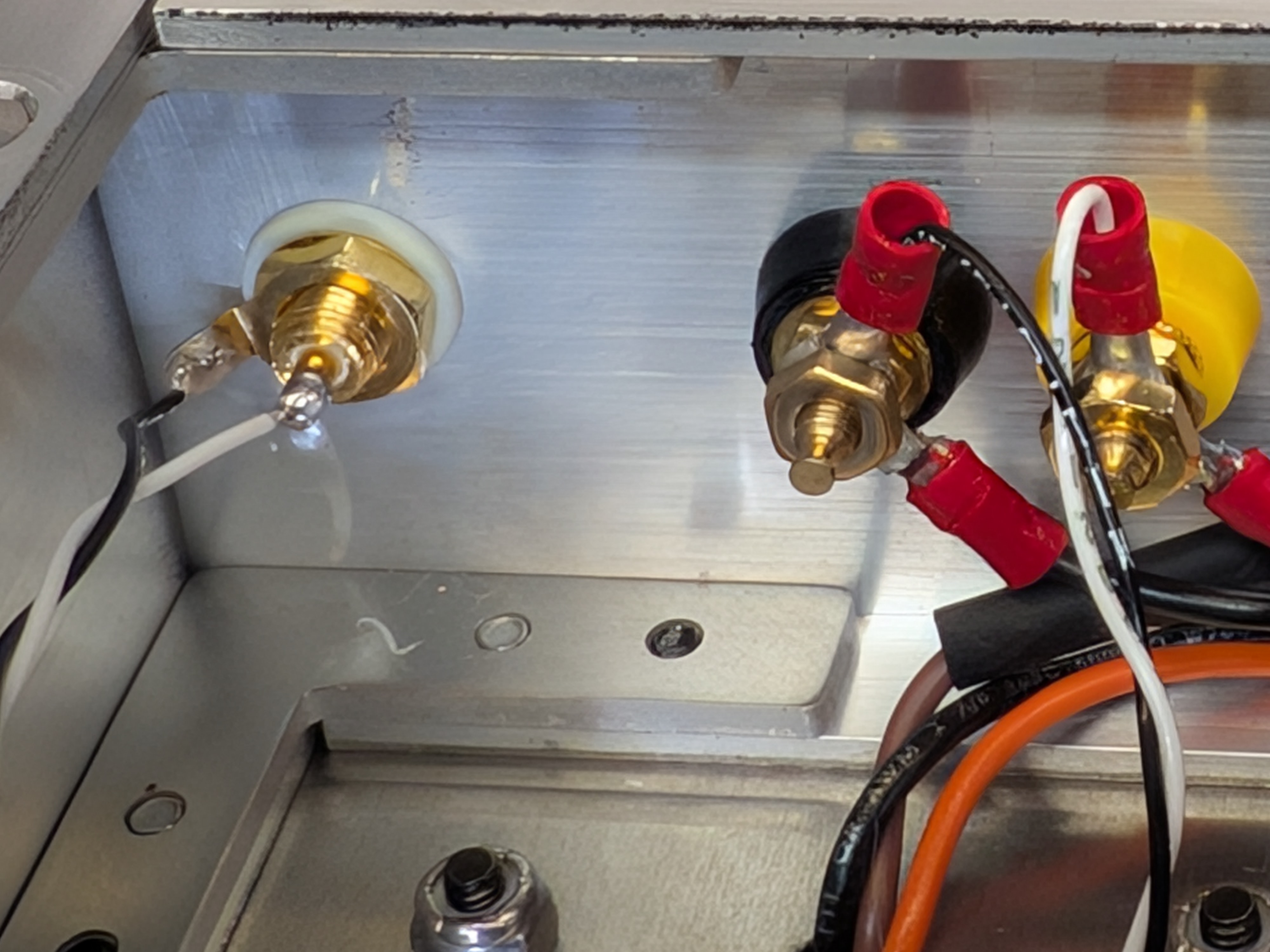
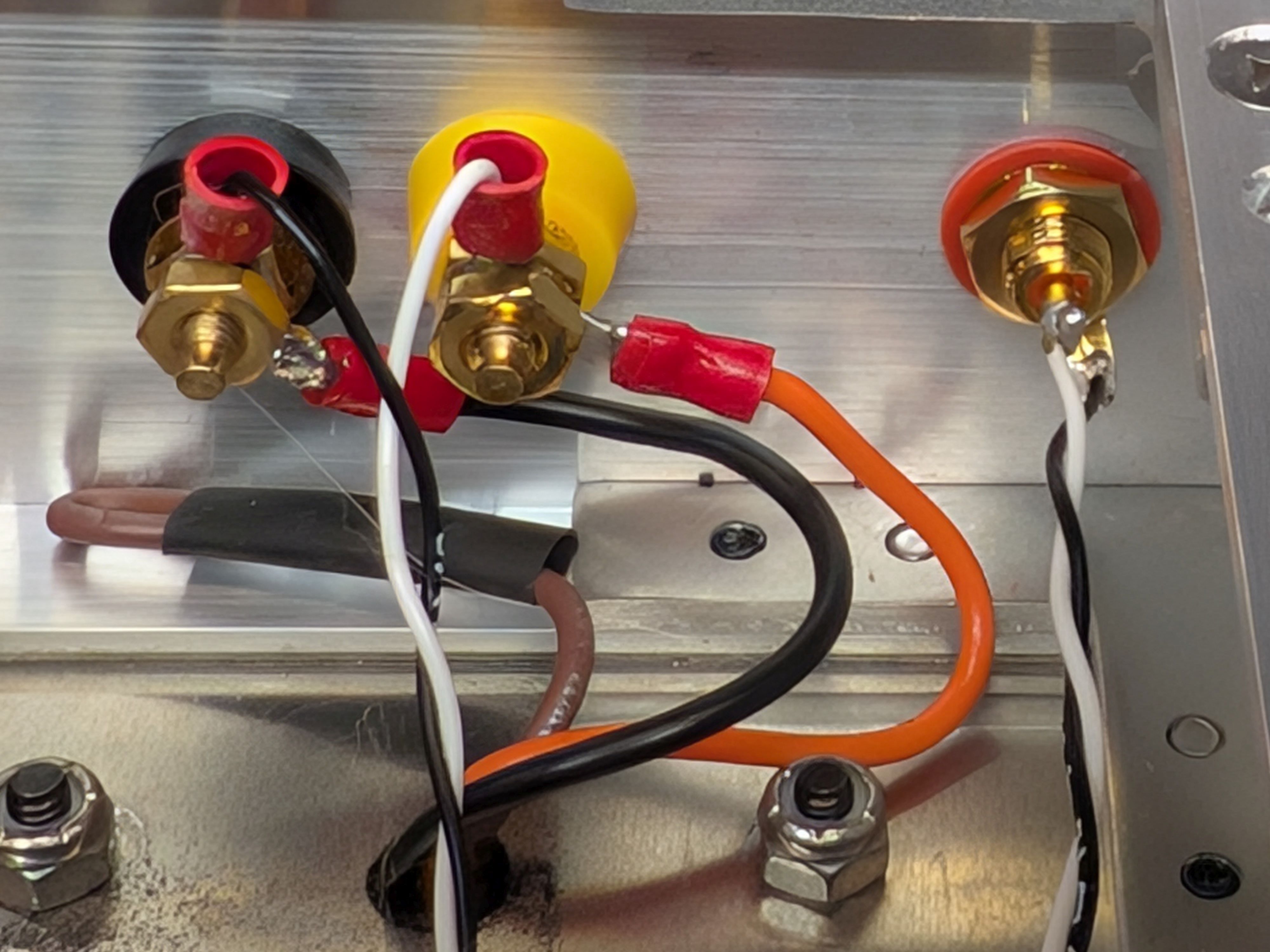
Here are some construction photos showing the guts (linked to larger images if you click on them):

Measurements
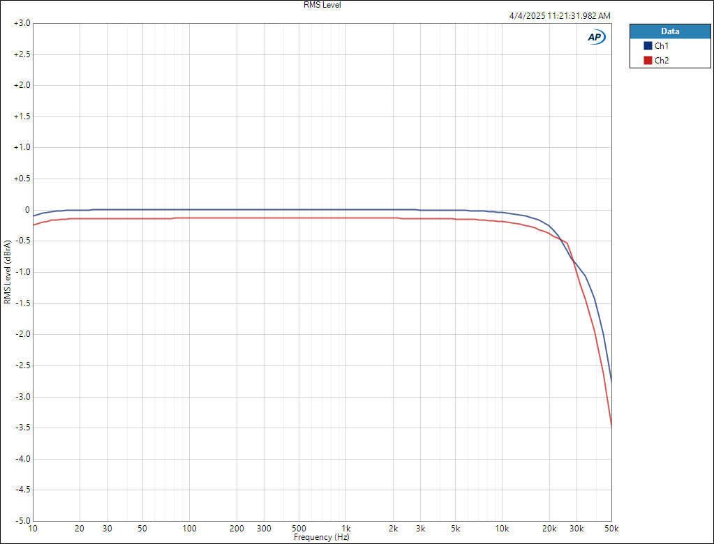
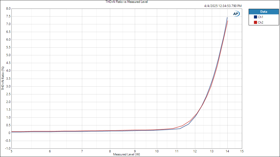
I'm really happy with the performance of this circuit. It puts out about 14 watts at clipping, and has around 0.02-0.03% THD at 1 watt. Frequency response is flat within 1/2 dB from 10Hz to 20kHz.
Here's THD vs. power output:
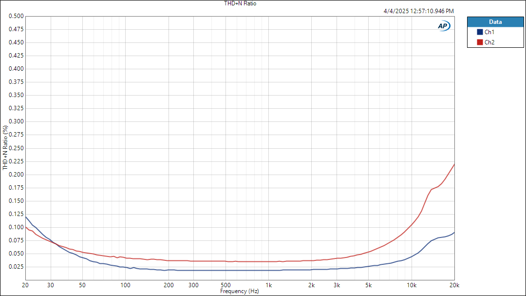
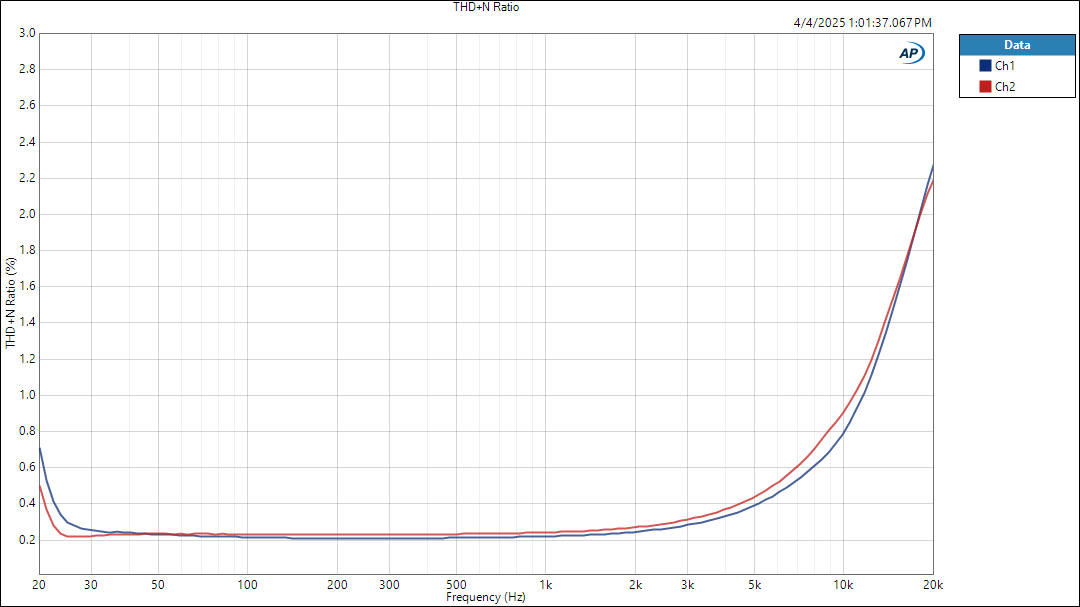
THD vs. frequency at 1 watt out:
...and at 10W:
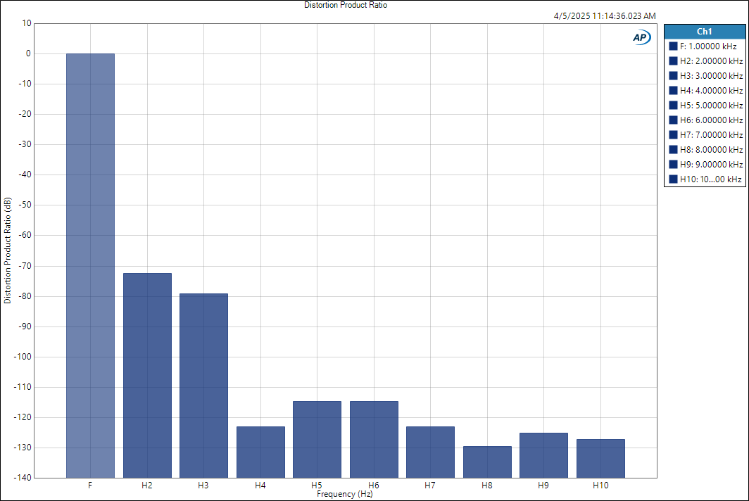
Harmonic distortion product ratios:
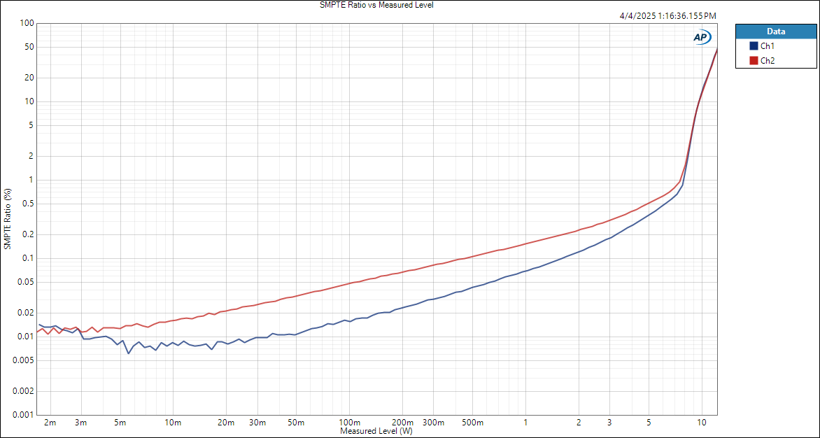
IMD vs. power:
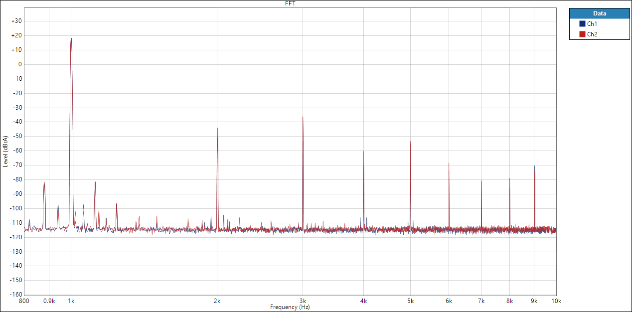
And finally an FFT, at 1W:
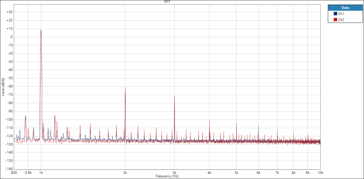
...and 10W:
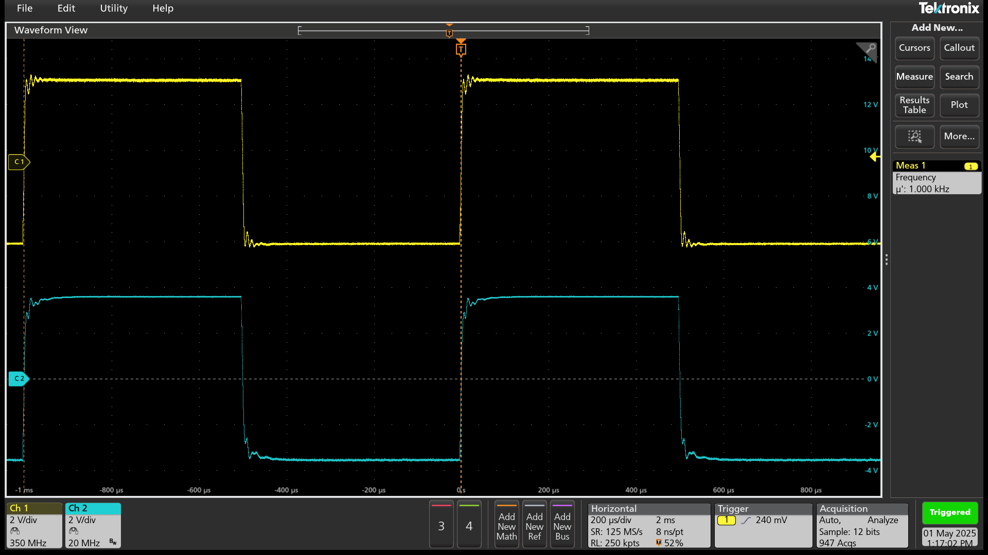
Here is the response to a 1kHz square wave, with the Pacific OPT:
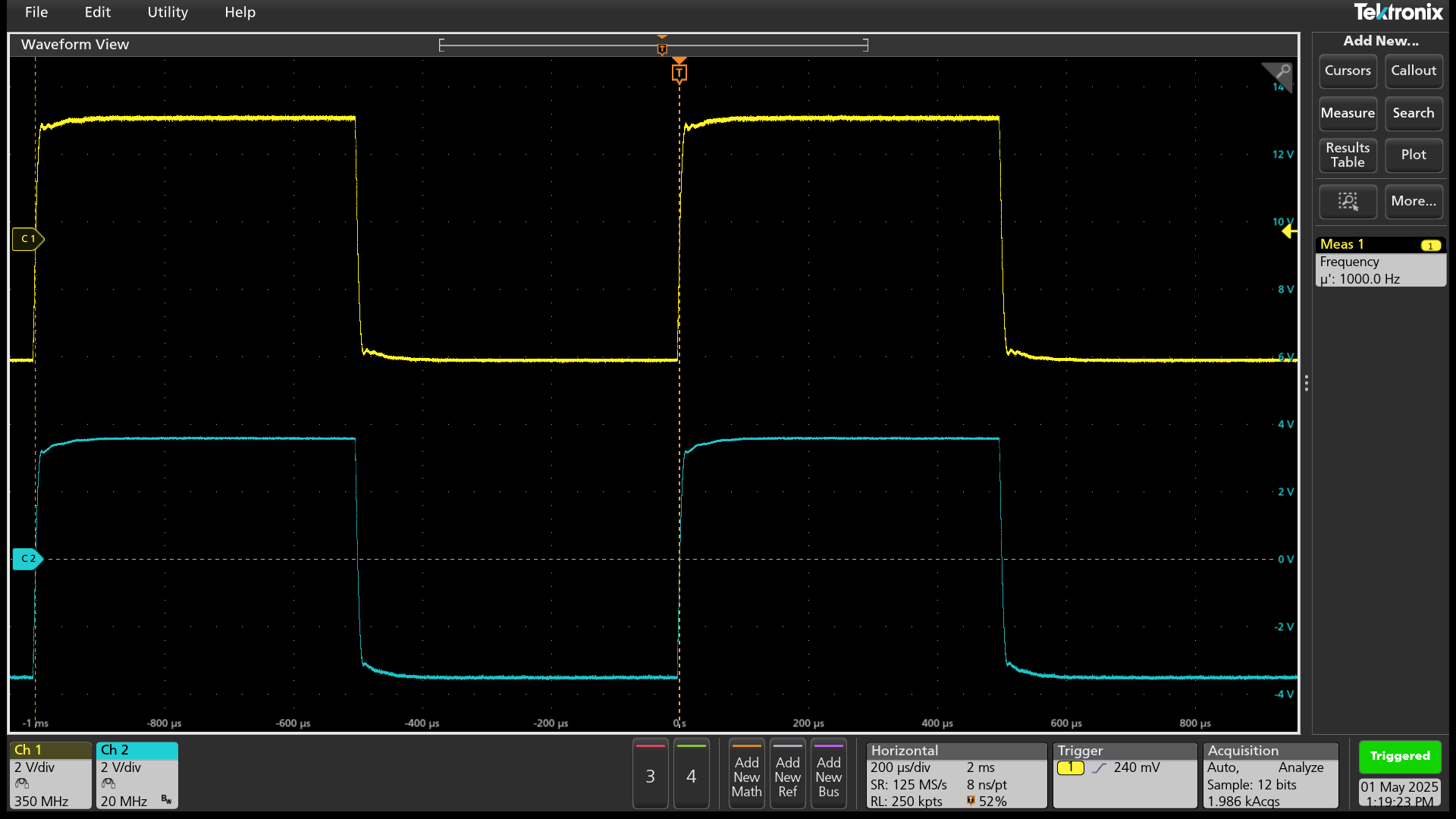
...and the MPS OPT: