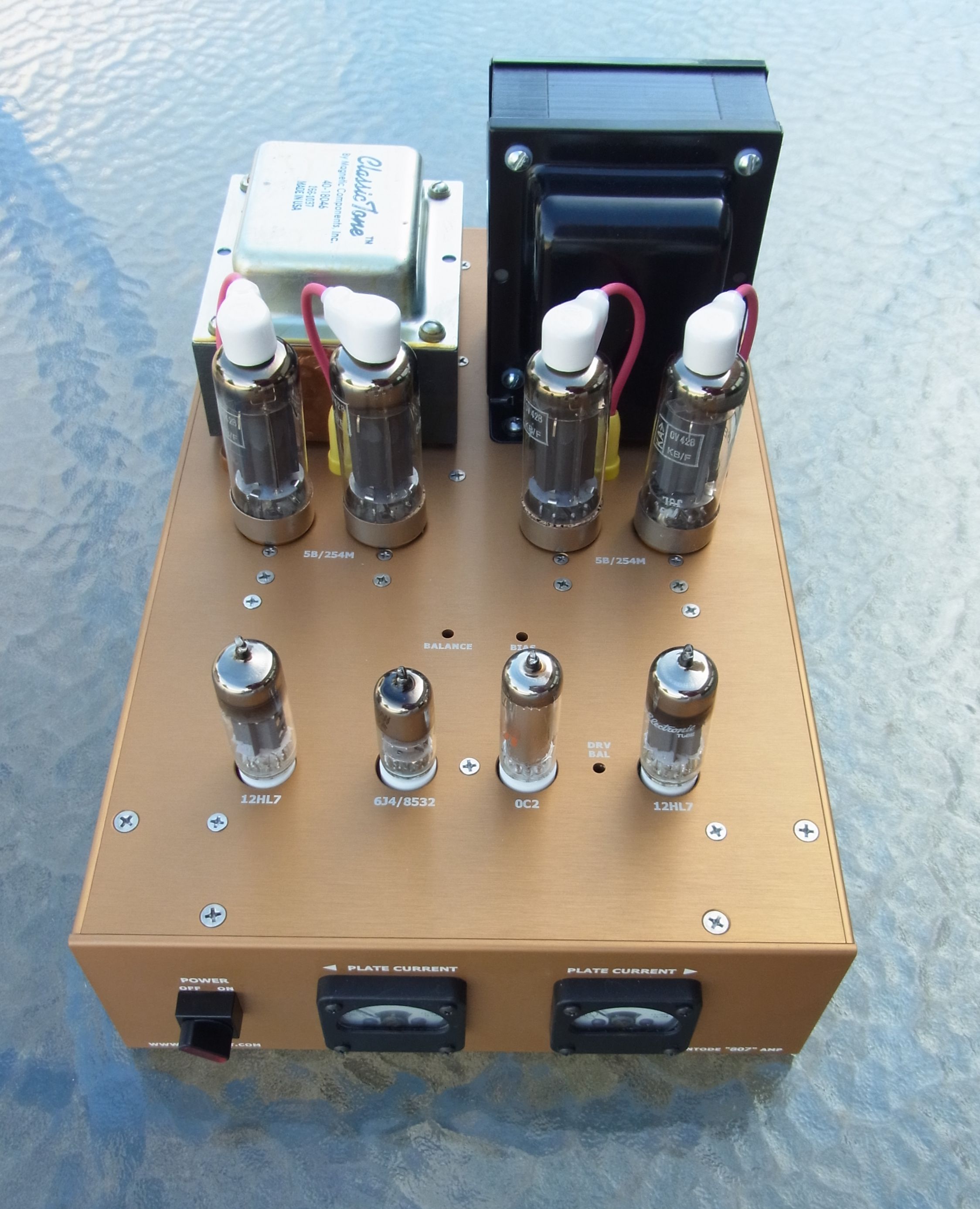
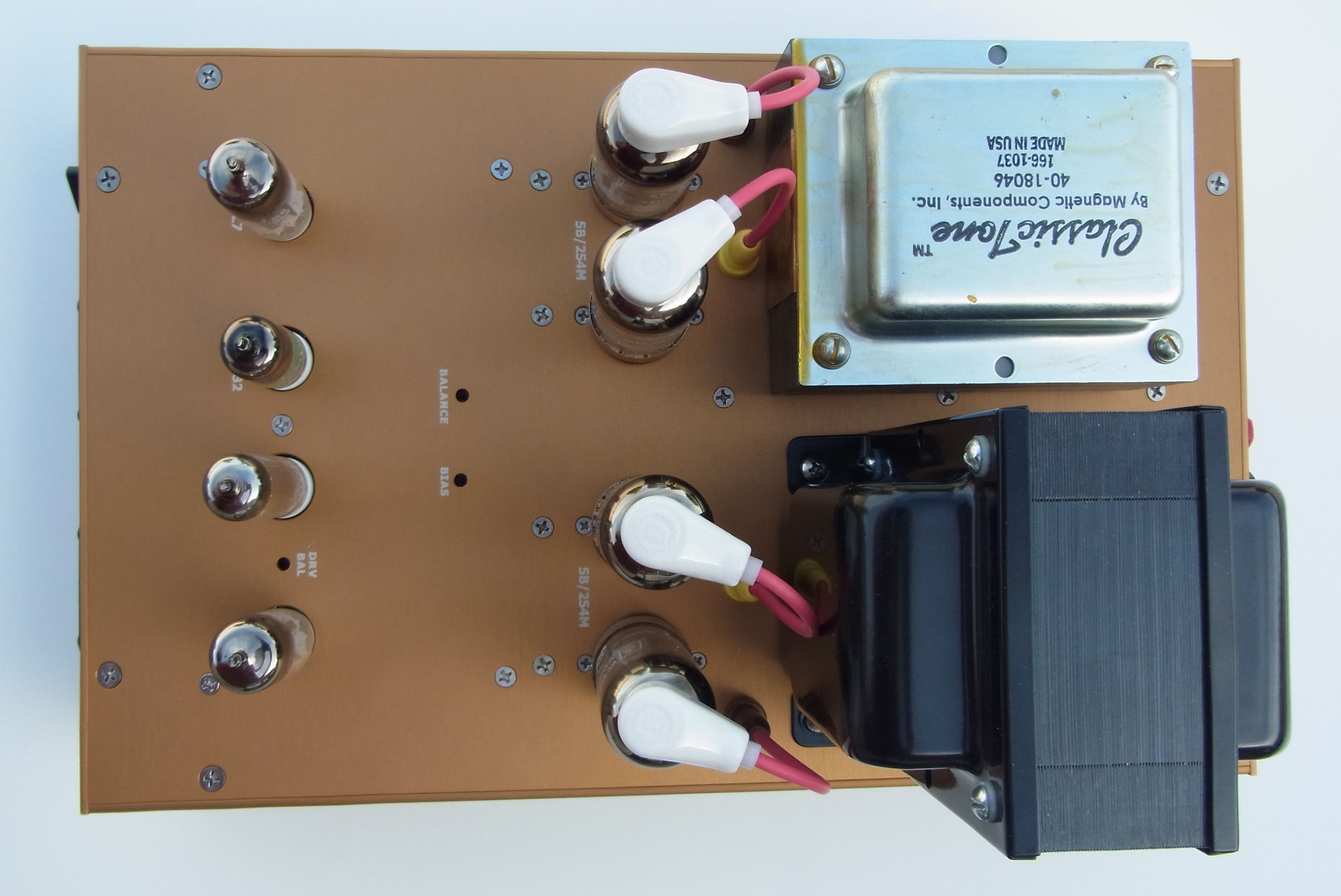
"807" Push-Pull amp (5B/254M tubes driven by the Push-Pull driver board)
(Click on the photos for full-size images)

This is a pair of monoblock amplifiers that I built using the Push-Pull driver boards (described in more detail here).
I used a push-pull-parallel set of 5B/854M tubes, which are basically 807 tubes in a slim bottle with a loctal base. 807's or 5933s can be substituted, as can 6L6 tubes or even 829B tubes.
The Circuit
Download a PDF schematic of the amp wiring, the driver PCB schematic showing components for this build, and the power supply PCB schematic.
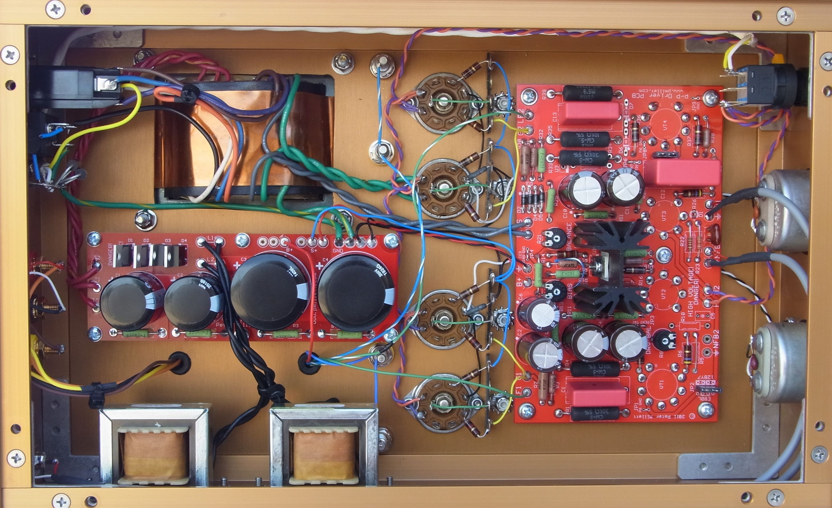
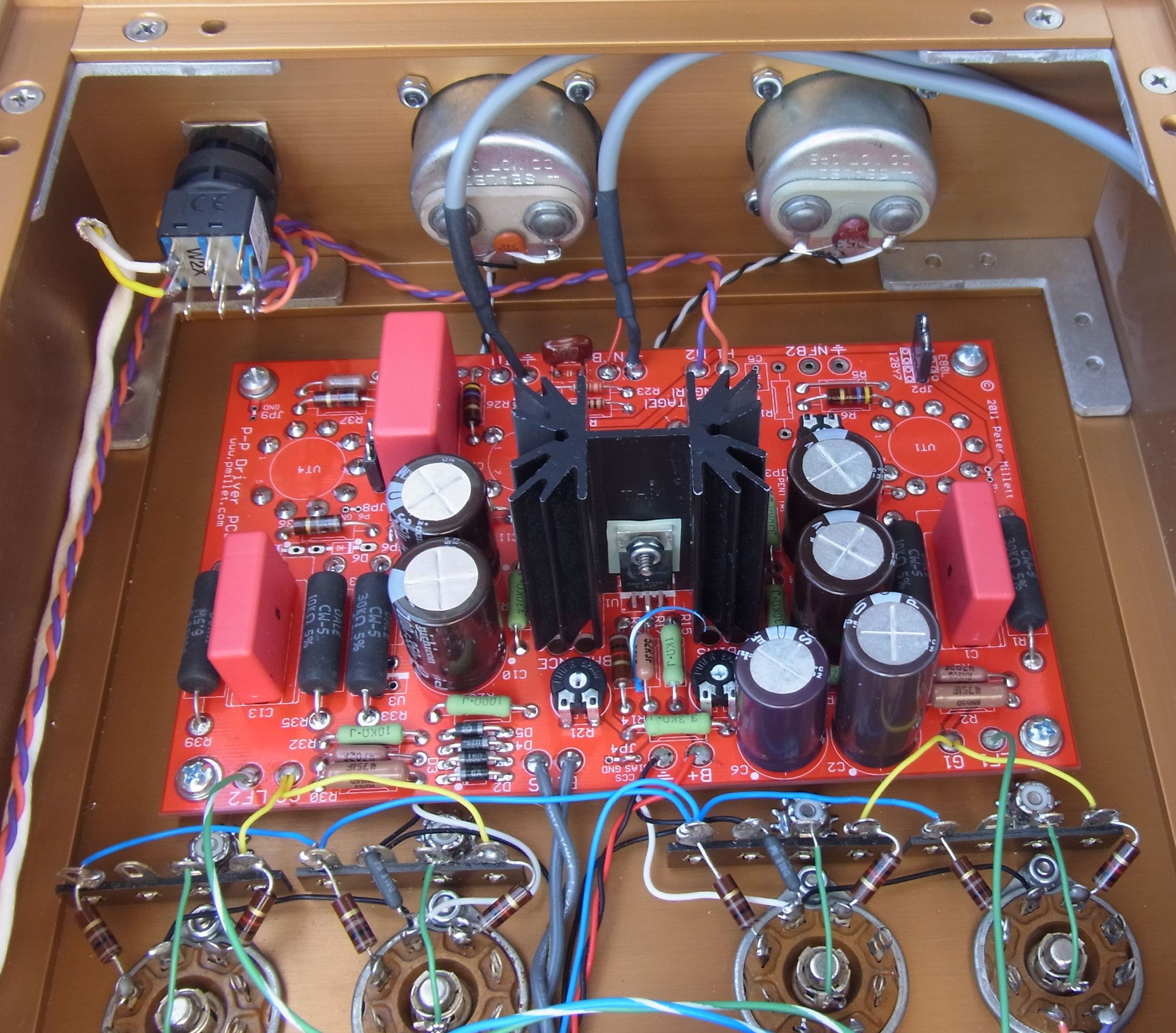
Here's a view of the entire inside of the chassis (click for higher res):
You can see the power supply board and chokes (lower left corner), AC input and power transformer (upper left), tube sockets (middle), and the driver board (right). Also visible are the power switch (upper right) and plate current meters (right). The OPT wiring can be seen emerging through black grommets just above the chokes.
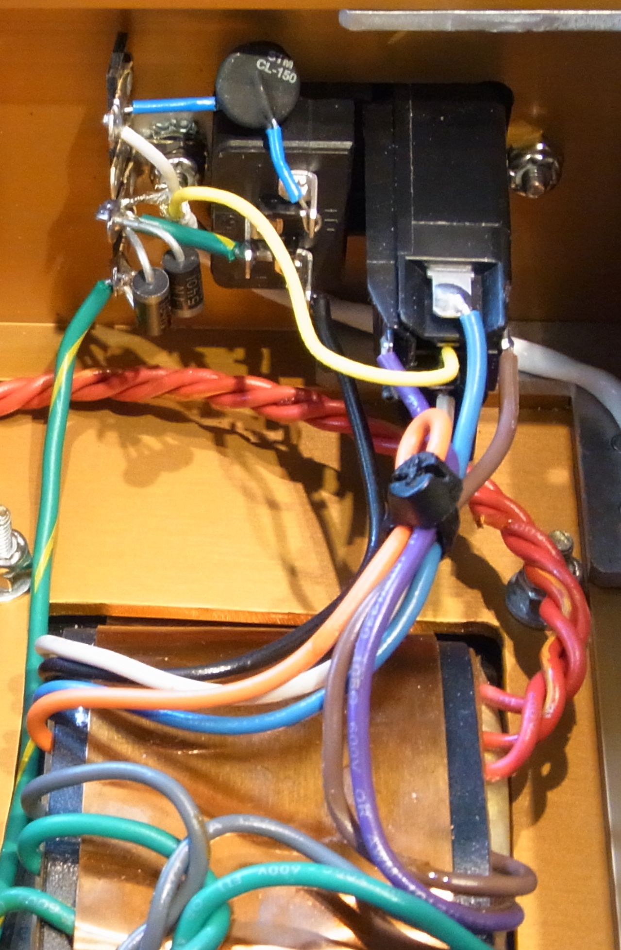
AC input
I used a Schurter type KEC AC inlet, which has a multi-pole voltage selector that is compatible with the transformer I used. the power transformer is a replacement transformer for a Marshall 100W guitar amp, a "Classic Tone" 40-18046. This stocked transformer (mine came from Triode Electronics) gave me exactly the windings I needed, without having to wait for a custom. You can, of course, as Edcor to make one for you as well.
D1 and D2 comprise a "ground breaker" circuit, which lets the amps ground float +/- a diode from from the AC mains ground. You may also just connect the grounds together. RV1 is an inrush current limiter, CL-150. It helps limit the surge at start-up. The fancy power switch is from Idec - part number LA2F-2C62-R. This integrates a switch and an AC/DC LED lamp. It is expensive (~$40) but I'm a sucker for a nice power switch ;) If you want to use this I'd recommend buying directly from Idec - they assemble them to order, which only takes a week or so.
The inrush limiter is mounted between the AC inlet and a small terminal strip, to which the diodes are also mounted. I used several of this type of strip in the amp - it is a Keystone type 812, available from the usual sources. The center terminal is used to provide a chassis ground connection. For safety it is important to have good contact here - note the use of a sharp lockwasher and the removal of the anodizing from the chassis.
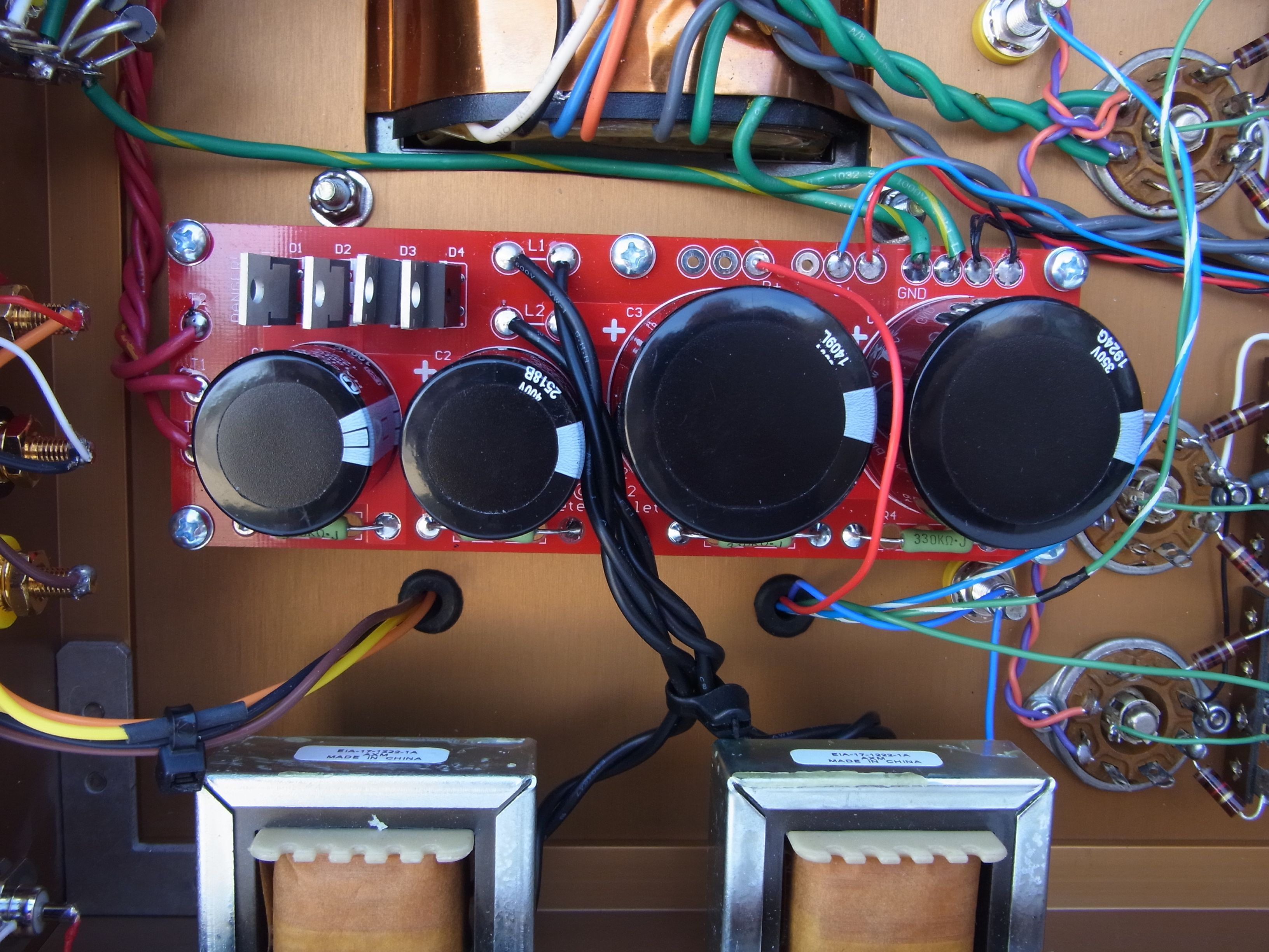
I made a power supply PCB for this type of amplifier. It uses a full-wave bridge and a center-tapped transformer to give you two DC voltages, one for B+, and the other for screen grids and to supply the driver. This way you can use a pretty high voltage on the plates (up to 600V for an 807), and still have a reasonable voltage (half of that) for screen grids and to power the driver.
Here is a BOM of the power supply, in .XLS or .PDF form. You can buy the PCB on eBay.
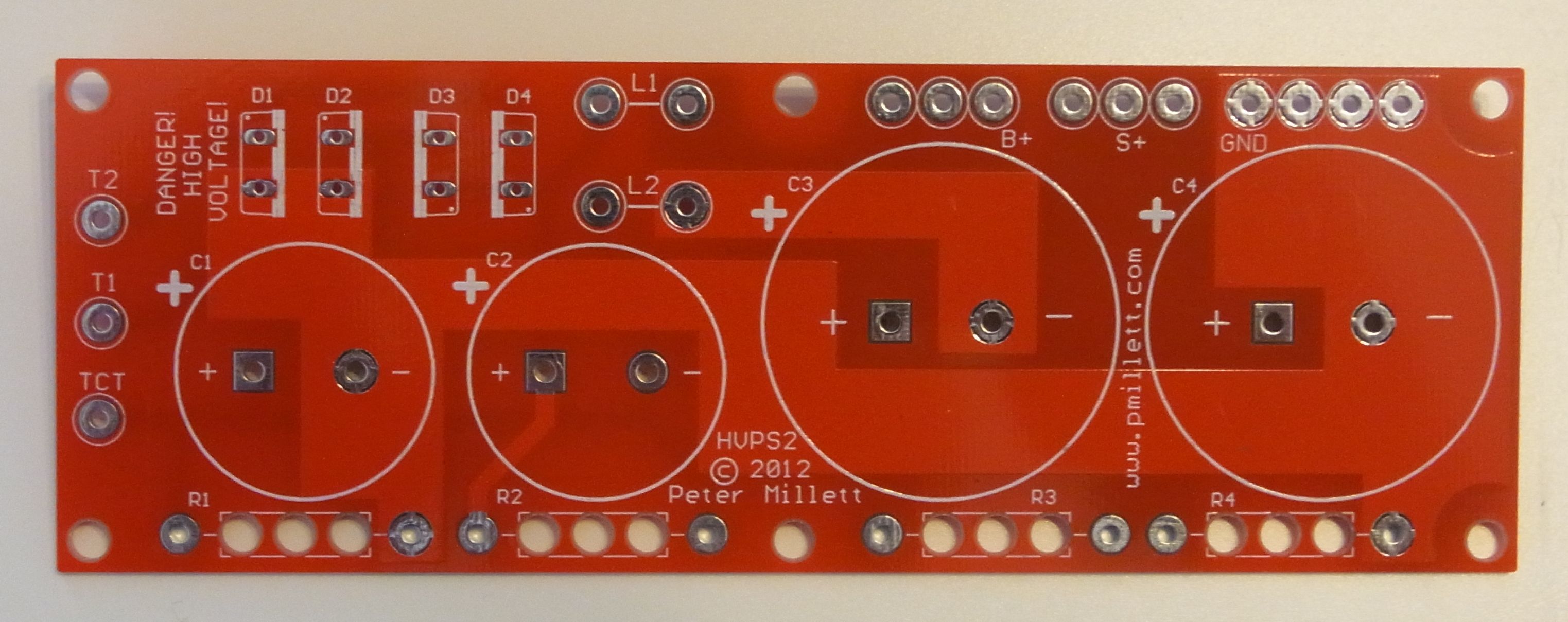
Four SiC TO-220 rectifiers are used. I used 1200V parts just in case I wanted to go crazy with the plate voltage. The first set of caps are 100uF, 400V parts, and the second 470uF, 350V. They are series connected so are good for B+ voltages up to 600V or so. Chokes are Triad C-24X, "cheap and cheerful" and available form Mouser (there is also a Hammond equivalent, type 156R). Exact specs are not critical, around 1H 200mA.
The chokes are mounted to the chassis side as shown below.
The driver board
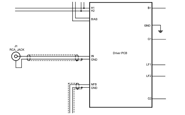
The driver board is described in more detail on its own page. You can download a schematic that has some of the unused parts deleted for clarity, as well as the correct part values for this amplifier.
Power connections to the driver board include the bias winding, the filament winding, and the lower-voltage screen supply from the power supply board. The input is wired using shielded cable (the gray cable in the photo below) from a jack on the rear.
Similarly, NFB is wired from the 8 ohm output to the NFB input on the PCB. You can see this in the photo below.

Output Tubes
Connections are made to the grids of the output tube through grid stopper resistors (1k carbon comps) mounted between the tube sockets and terminal strips, which are then connected to the driver board with wires, as shown below:
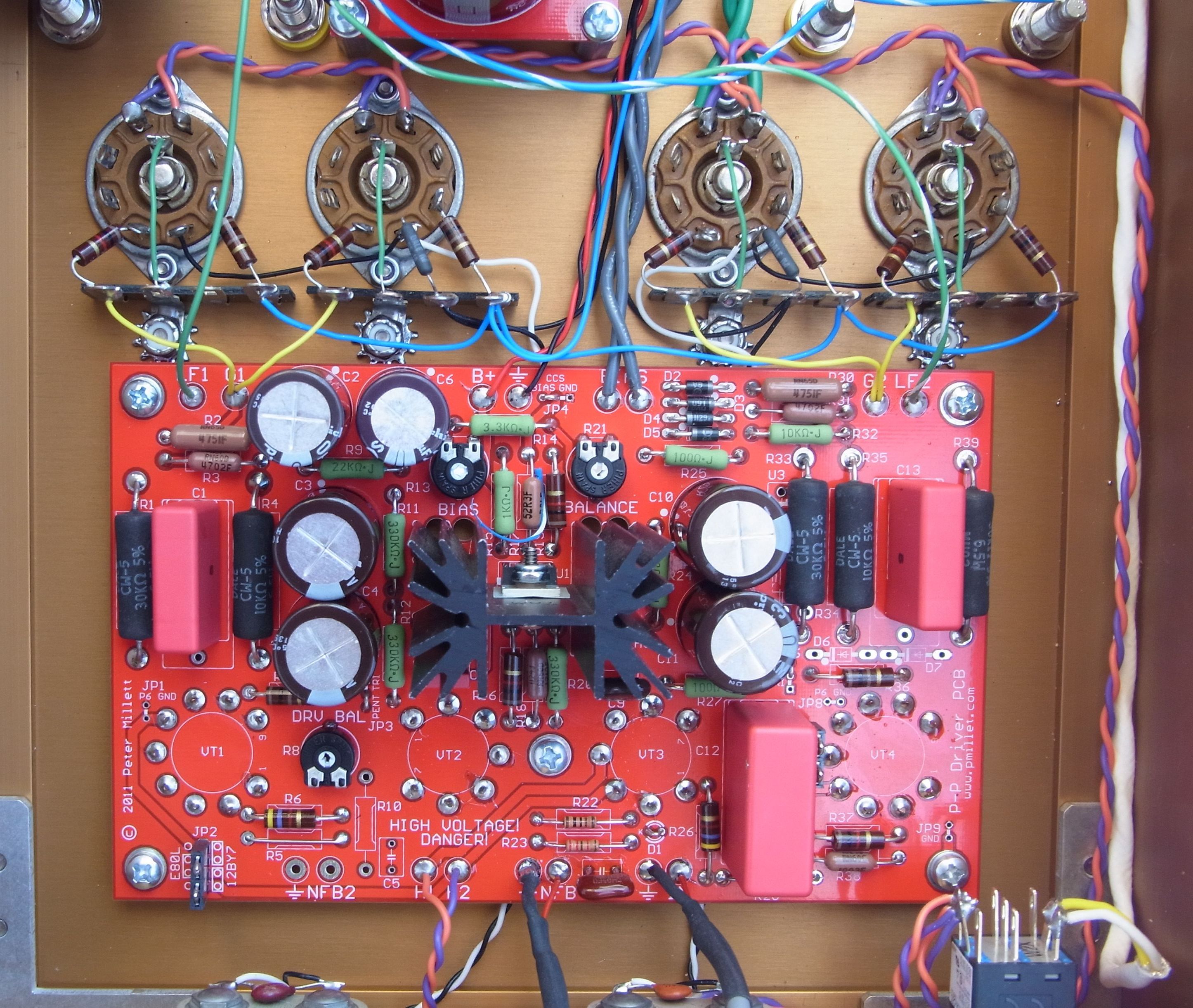
Grid stoppers (100 ohm carbon comp) are also used on the screen grids, again mounted between the tube socket and a terminal strip.
Note the 1 ohm resistors between the cathodes of each parallel pair of tubes and ground. This is for current measurement. 1 ohm gives you 100mV across it at 100mA plate current. In my case, I used a pair of 100uA panel meters with an internal resistance of 1200 ohms, so I used 1.2 ohm shunt resistors to make the meter read 100mA full scale. Different meters will need a different shunt. If you are just reading voltage using a voltmeter (a DMM, for example), 1 ohm is good.
Since the plate connection of these tubes is on a top cap, I mounted banana jacks on the chassis and made little wires that connect the plate cap to a banana plug. This made wiring cleaner. In the photo above you can see two of the banana jacks, connecting to one side of the OPT.
Output Transformers
I used some Dynaco replacement transformers for the OPTs. This transformer (A-431-S, from Triode Electronics) has a 4300 ohm primary, and is good for between 60 and 100 watts. Its big... and this amp is flat to below 5Hz using them!
I used the screen grid taps to provide local feedback to the driver. They DO NOT go to the screen grids of the tubes... though if you want to do ultralinear connection, you certainly can try it - but not with an 807, whch has a maximum screen voltage of 300V.
Global feedback is taken from the 8 ohm tap and fed with a shielded cable back to the driver. Note that this is the ground connection for the output - this connection is important!
The Chassis
I built the amps into a semi-custom chassis from Landfall Systems. This is a very nice, heavy chassis made to order in your dimensions from a standard set of extrusions.
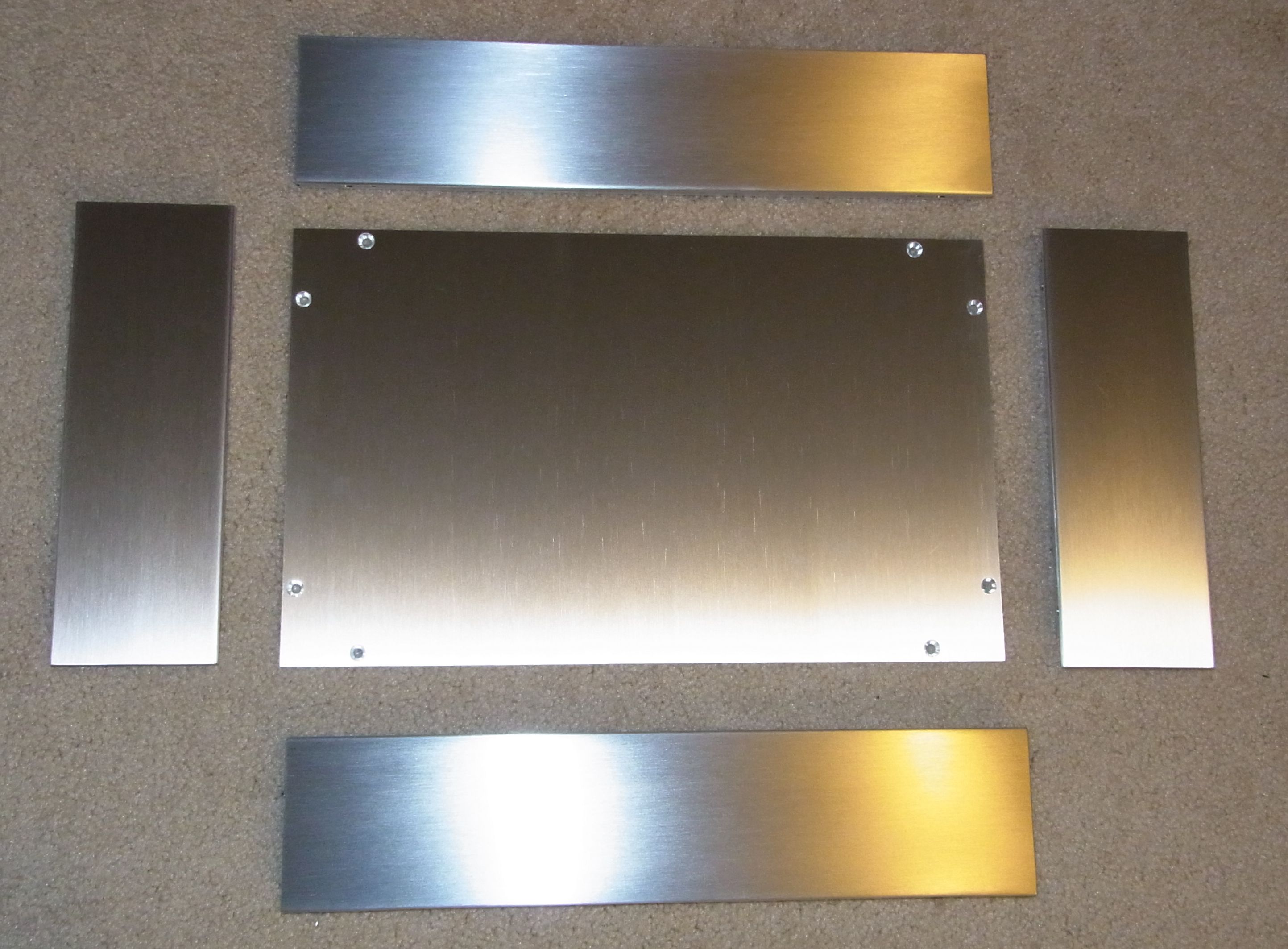
Here's the chassis as I received it:
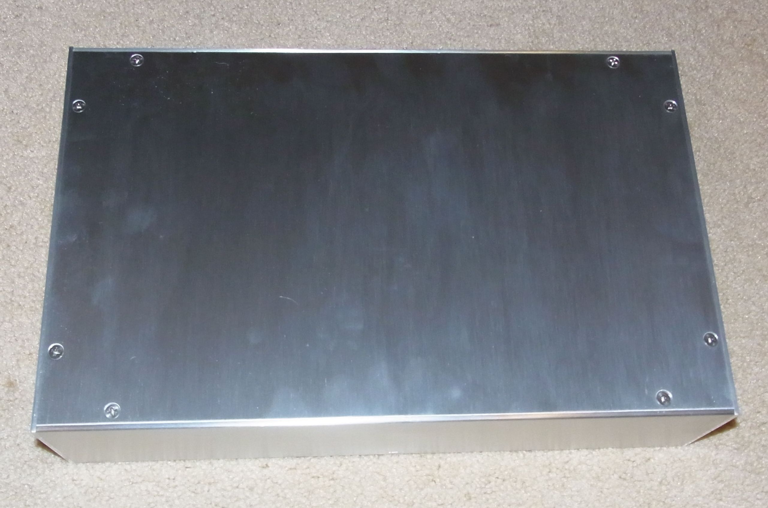
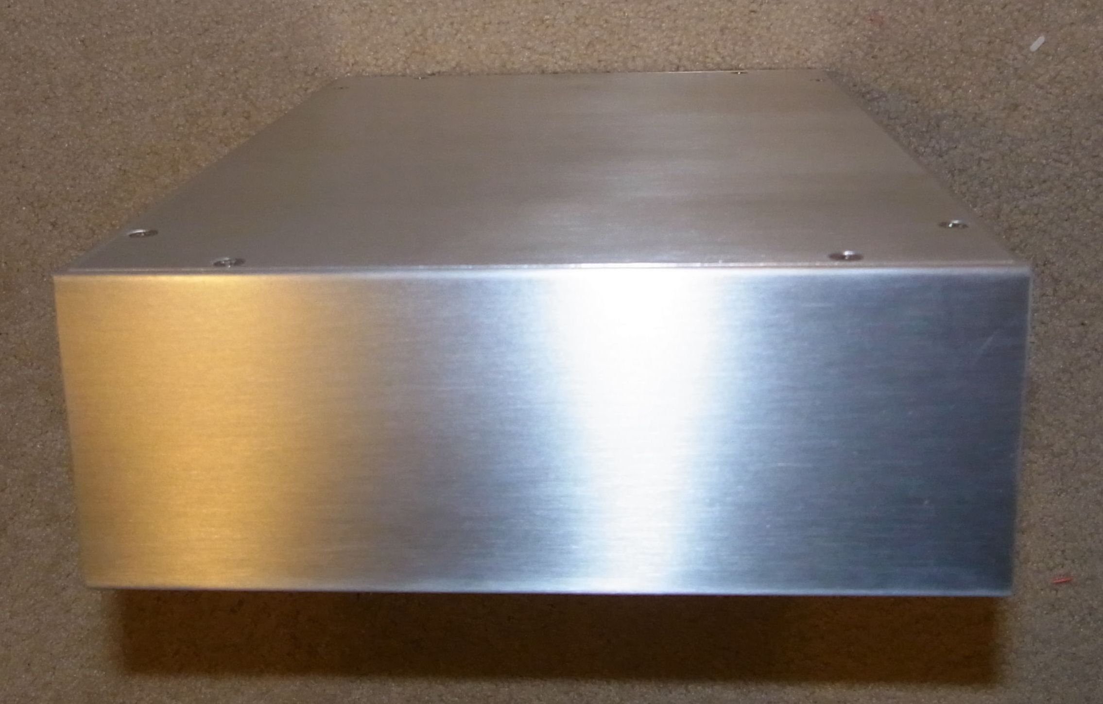

One of the great things about this chassis is that it disassembles, so it's easy to cut and drill holes in the sides and front. Anybody that's balanced a chassis the long way on a drill press knows what I mean!
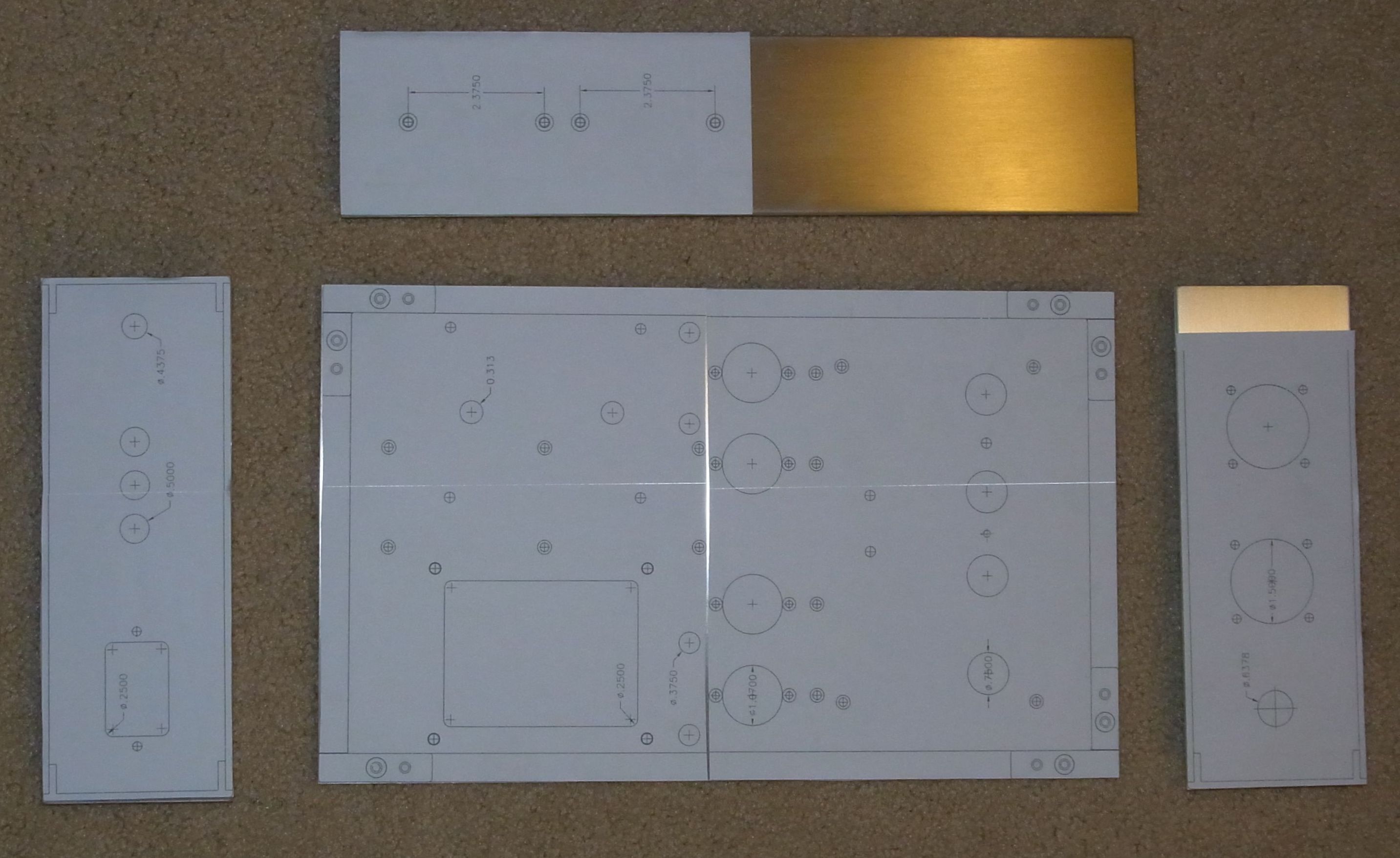
I did a layout of the entire amp using AutoCAD. Then I printed the chassis layout onto label stock, and stuck them to the parts. This made a guide to allow me to drill and cut the needed cutouts, using a drill press, hole saws, unitbit, chassis punches, and a jigsaw (for the big cutouts):
You can download my layout in AutoCAD 2000 DXF (zipped) of the entire amp (caution, it's big, it has the PCBs in it), or just the chassis, or as a set of individual PDF files: Front, Rear, Side, Top. The PDF files are scaled 1X and you should be able to print them at the correct scale - measure the plots and see if you have to adjust for your printer.
After I cut and drilled the chassis, I sent them back to Landfall, who brushed and anodized them (the color is "bronze"). After anodizing, I had them laser engraved to provide the labels. The result is really nice looking, at least to me. You can download the artwork (zipped Corel Draw file) if you want to do this yourself. Landfall can help you do the laser engraving.
Measurements
This amp design uses a lot of negative feedback. I know that is not some people's "cup of tea". But I suspect that many people who think it sounds bad have been listening to bad implementations. It is not an easy thing to get the feedback right... and it also depends on not just the circuit but also the transformers used.
Anyway, it sounds good to me, and to everybody that's listened to it so far :)
I made a series of measurements using my Rohde & Schwarz UPL audio analyzer:
Frequency response at 1W into 8 ohms. -3dB are at <5Hz and ~85kHz.
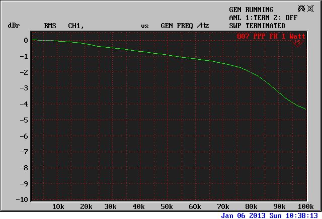
A zoomed in view... -0.25dB at 20kHz
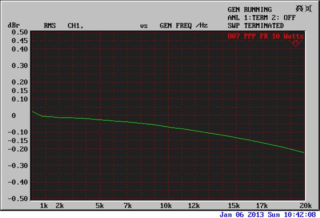
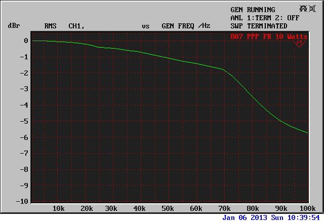
Frequency response at 10W into 8 ohms. -3dB are at <10Hz and ~55kHz.
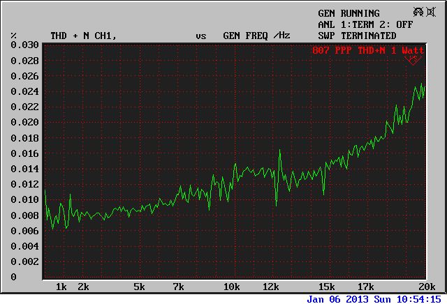
THD+N vs. frequency at 1 watt into 8 ohms
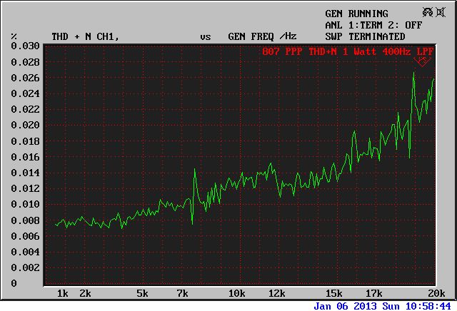
Same plot with high-pass filter enabled at 400Hz to remove environmental 60Hz and hum
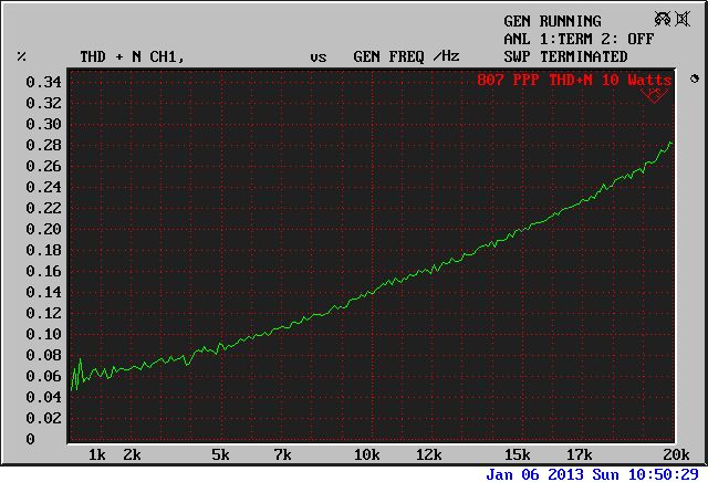
THD+N vs. frequency at 10 watts into 8 ohms. Nice, low, and so surprises.
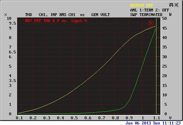
THD (green) and output power (yellow) into 8 ohms vs. input voltage. Onset of clipping is around 40 watts.
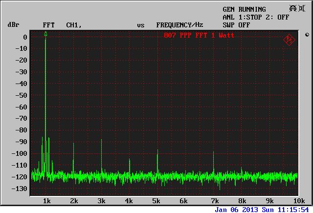
FFT of 1kHz, 1 watt into 8 ohms.
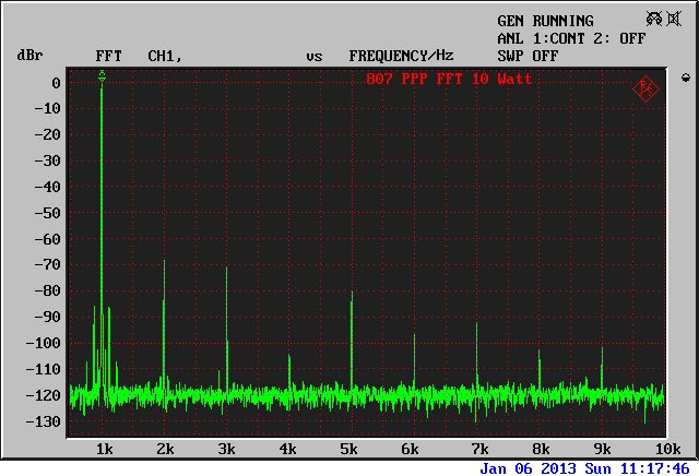
FFT of 1kHz, 10 watts into 8 ohms.
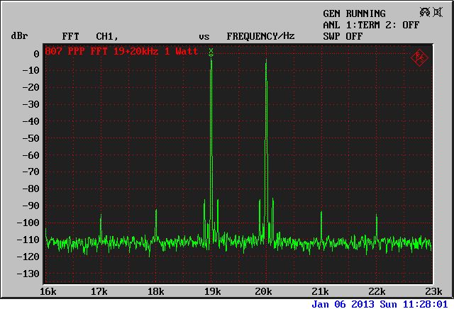
FFT of 19+20kHz IMD signal at 1W into 8 ohms
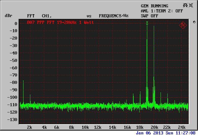
Same, zoomed in to show sidebands
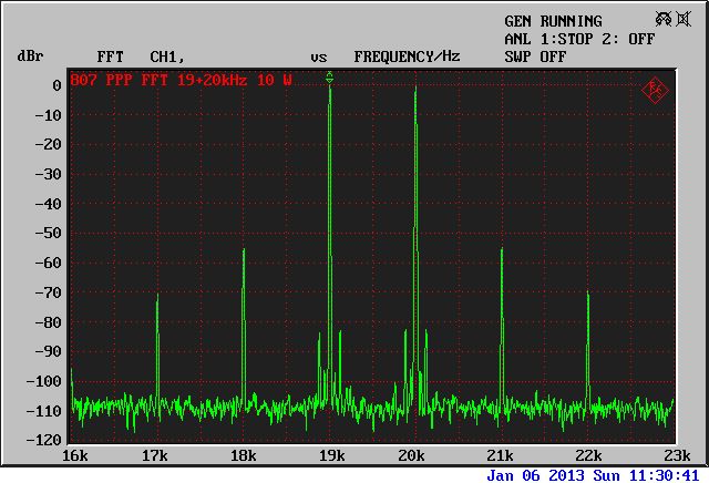
FFT of 19+20kHz IMD signal at 10W into 8 ohms
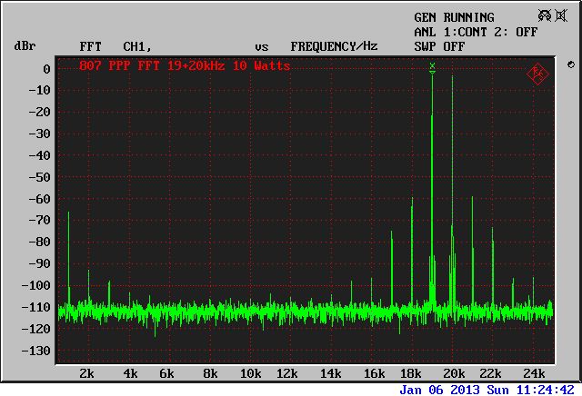
Same, zoomed in to show sidebands. Highest product is -55dB!