An all-tube, 4-pole active crossover
PLEASE READ - Commercial usage of information on this site:
I consider all the information that I post here to be in the public domain. So, you can use it however you want, for commercial or non-commercial use.
That said, I would appreciate it if you at least let me know if you are going to use any of the circuits or especially PCB Gerber files to make commercial products, or to sell bare PCB's.
There are some cases where products are being sold not only with my permission, but active involvement. The "Millett Hybrid" effort and others at HeadFi are examples (and excellent models of how the DIY community should work, in my opinion). There are other cases where I have asked vendors to sell PCB's as a service to hobbyists. And there are other cases where companies are manufacturing and selling PCB's, chassis, etc. without contacting me at all.
In ALL of these cases, I make no profit from any of the sales. Zero, zip, nada. I have a normal "day job" that pays the bills, this is strictly a hobby with me. So please do not expect me to provide the level of technical support that you might expect when buying a product. I try and help, but it sometimes takes me days - even weeks if I'm traveling for work - to respond.
Thanks for your indulgence in reading this!
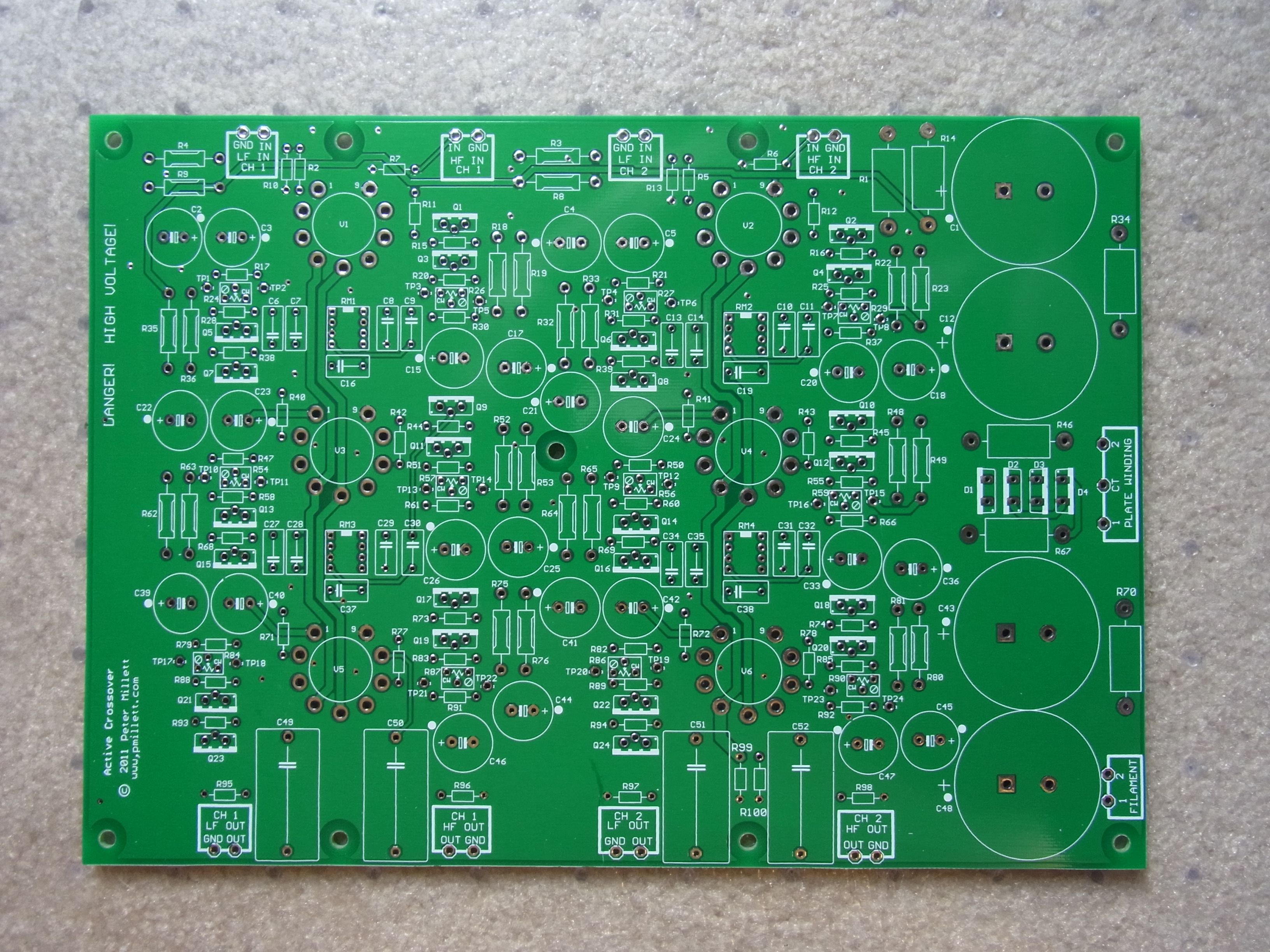
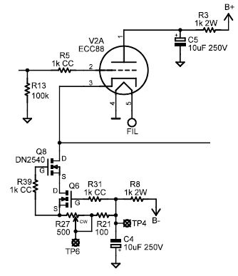
UPDATE 12/19/11 - I had several requests to update this PCB, so I did. The tubes were changed to ECC88 (or anything else that fits that base pinout), and used cascode CCSs (using DN3540s) instead of the resistive loads on the cathode followers.
Now, I have NOT built or measured this myself, but I have provided boards to a couple of people, and reportedly it works :)
I have a couple of pairs of boards left that I'll put up on eBay - if there is interest I'll build more.
Here is an updated PDF schematic. Also, the bill of materials, a PDF of the PCB, and the PCB dimensions.
The rest of the info on this page still applies (like how to set the frequencies).
I originally designed this active crossover with the intent of doing a magazine article about it. I never did write the article, partly for reasons outlined below.
Even though this project turned out exactly as designed, I've never been that happy with it, for a couple of reasons: The main one is that, after building and testing it, I found that I preferred the sound (at least of my existing speakers) with their purpose-designed built-in passive crossovers! I expect that if you had some speakers that were designed to be driven with separate amps and an active crossover, this would be a fine design for it. On paper it performs very well. The only technical area where I am somewhat unhappy with it is that it's a tad noisier that I'd like. I'm sure that this can be addressed, but since I really didn't like the sound in my system, I haven't put a lot of effort into it. I'm sure that a little work on the grounding and worst case putting the power supply in a separate box would cure the problem. I have very sensitive power amps (input about 2-300mV) so it's worse in my system than most.
The design
Let me start by saying that I'm not a filter expert. I've certainly designed many active filters in my career, but I don't have an understanding of the complex mathematics involved, so I'm basically a cookbook filter designer. I took standard filter design and put in tubes as the active elements.
For a very good text about designing active filters, look at this from Texas Instruments - "Active Filter Design Techniques", excerpted from "OpAmps For Everyone", also an excellent book. Although this describes filter design using opamps, the principles all apply to tube circuits as well. Another good reference is Application Note OA-26 from National Semiconductor.
This crossover is a stereo pair of two-way filters (high-pass and low-pass), using a Sallen-key circuit implementing a linkwitz filter. 12AU7 (or 5814) tubes are used as cathode follower buffers between filter sections. It runs on a +/- 100V (more or less) power supply.
The Sallen-Key circuit was chosen for it's simplicity, and the Linkwitz filter is used so that the phase shift through the high-pass and low-pass sections are equal at the crossover frequency. If you have a phase difference between the filters at the crossover, you will get an anomaly in response there (worst case, a "suckout", or deep notch in the response, if there is a 180 degree difference).
In simplified form, the filters look like this:
The amplifiers are shown as generic blocks. In practice, they could be implemented with an opamp follower, a transistor emitter follower, FET source follower, or (as in this case) a tube cathode follower. They are all unity gain amplifiers with high input impedance and low output impedance, and their purpose is simply to keep anything connected to the output (which may be another filter stage) from loading, and thus changing the response of, the filter section. Note that there are also active filter circuits that employ gain... most opamp active filters do.
Each of these filter section is a 2-pole filter. There is a mathematical origin of this term "pole", but you can think of each pole existing because of a capacitor (or inductor). Since there are two capacitors in both the low-pass and high-pass circuits, each are two-pole filters. Note that a single RC filter is a single-pole filter, and an LC filter is a two-pole filter.
A filter has an ultimate rolloff of 6dB per octave (an octave is a doubling of frequency) per pole, so a 2-pole filter has a rolloff of 12dB/octave. If you cascade two 2-pole filters, you get a 4-pole filter, which rolls of at 24dB/octave. This crossover is exactly that: 4-pole filters (one high-pass and one low-pass per channel), using two cascaded 2-pole filters as shown above, to get a rolloff of 24dB/octave. In this example, with a crossover frequency of 2300Hz, the high pass would be down 24dB at 1150Hz, and the low pass down 24dB at 4600Hz.
The capacitor shown as "2C" has twice the capacitance of the cap "C", and likewise the resistor shown as "2R" has twice the resistance of the resistor "R". For details about these component values, see below.
Here is the schematic for the entire active crossover (263kB PDF file)
And a BOM in .XLS or .PDF form - sorry, not very detailed, just what Eagle CAD kicks out.
The frequency-determining elements are all resistors and capacitors. I put the resistors on little DIP headers so that it would be easy to change them, to change the crossover frequency. Most normal frequencies can be accommodated by just changing the resistors, but some might require different capacitors. My circuit was set up to cross over at 2300Hz. Refer to the section below about Setting Crossover Frequency to figure out hot to set the frequency for your application..
I ran spice simulations for the circuit, using both 12AU7 tubes (running at 9mA) and 12AX7 tubes (running at 1mA). The resultant gain/phase is shown below:
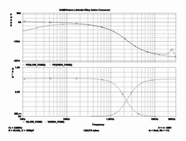
Simulation result, 12AU7. Click here for a more readable version (83kB PDF file)
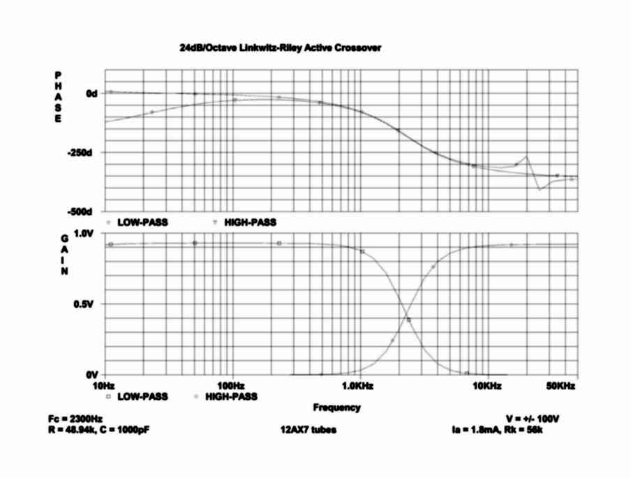
Simulation result, 12AX7. Click here for a more readable version (83kB PDF file)
Note that there isn't much difference between the two, but one thing I did on the 12AX7 circuit was to pre-compensate the gains so that they matched between the low-pass and high-pass sections. The 12AX7 cathode follower has a much higher output impedance, so to get this match I had to muck around adding some resistors to get the gains to match. In the 12AU7 circuit, I did no matching. You can see in the response curves that the 12AU7 high-pass output is slightly lower than the low-pass... the 12AX7 (before compensating for the Zout) was a good 3dB down on the high-pass side, where the 12AU7 is about 1dB. For these reasons, I decided to use 12AU7 tubes for this (actually I used GE 5814's). I'm sure 6922's or other tubes with medium mu and reasonably low Rp would work well also.
Note that in both cases the phase response is smooth, and equal at the crossover frequency. Note that you really don't care about the phase of the low-pass output far above crossover, nor the phase of the high-pass far below crossover; there will be no signal getting through the crossover at those frequencies. So the overall phase shift will be close to 0 at low frequencies, about 180 degrees at the crossover frequency, and a max of 270 degrees at the highest frequency.
The measured response of the crossover (using 12AU7 tubes) was very close to the simulation result, as shown below. The "bumps" on the plot are probably as much a matter of my measurement accuracy as anything - I took these numbers by hand and plotted them. I didn't measure the phase response, but have no reason to expect that it would be much different from the simulation either.
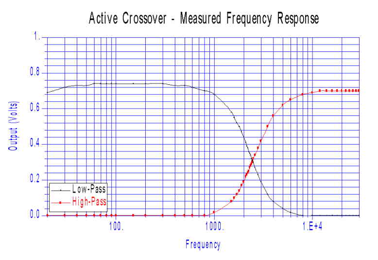
Measured frequency response
Setting the crossover frequency
As I mentioned, the crossover frequency is set by the resistor and capacitor values in the filter. For a 4-pole linkwitz filter, the first stage (2 poles) and the second stage (2 poles) are identical, making things much simpler. If you want to implement another filter type, read up (the two references above are great) to decide how to determine the part values.
The method used to pick the component values here is as follows:
1. Somewhat arbitrarily select the capacitor value C. I say "somewhat" arbitrarily, because the value of C affects the corresponding values of R needed, and you want to keep both in a range that is practical. If you pick a really small C you will wind up with resistors in the megohm range, the circuit may not work well do to the finite constraints on things like the tube input impedance, and leakage currents. You may also not be able to find the right part value as a "real" component.
For this design, I picked a C value of 0.001uF, or 1000pF. This value is pretty good for most 2-way crossovers. You may need to increase this to a larger value, like 0.01uF or 0.1uF if you need a very low crossover frequency (like for a subwoofer).
I just paralleled two capacitors of value C to get the capacitor of value 2C.
2. Calculate the value of resistor R (in ohms) by the following formula: R = 1 / (2*pi*1.414*f*C), where f is the desired crossover frequency in Hz, and C is the value of C in farads. This is the same as 1 / (8.886 * f * C).
Using my 2300Hz as an example and 0.001uF value for C, the R = 1 / (2*3.1416*1.414*2300*1x10e-9), or 48,937 ohms. The closest 1% resistor value to this is 48.7k ohms. 2R is 97,875 ohms, so 97.6k is the closest available. These are the values that I used in the simulations and measurements above.
The error caused by going to the nearest 1% resistor is negligible, but I would not use 5% or 10% resistors if you can avoid it. The capacitors really should be 1% as well, but 1% tolerance caps can be hard to find. I measured a batch of 20 0.001uF 10% polypropylene capacitors, and found that all but 4 measured within 1%. The ones that didn't were all within %&. except one was off by around 3%. You might be able to get some of the audiophile parts vendors to select caps for you, or if you can get your hands on an RCL bridge, you could measure them yourself... but odds are pretty good that even if you use 5% caps you won't see any noticeable problem.
You can also take the values I have above and just scale them linearly with frequency. The resistors get bigger for lower frequencies; i.e., the resistance in inversely proportional to the frequency. If you wanted a 4600Hz crossover (2 times 2300Hz) you would use resistors of 1/2 the value I did; similarly, for a frequency of 1150Hz (half 2300Hz) you would use resistors of twice the value I did. You can see from this if you want to go to a real low frequency, you may need to make the caps bigger. For example, at 100Hz using C=.001uF, R has to be 1.125M. This is probably too big, and will introduce errors. You'd be better off with a cap 10x as big (0.1uF) and a resistor 1/10 as big (11.25k).
More Pictures
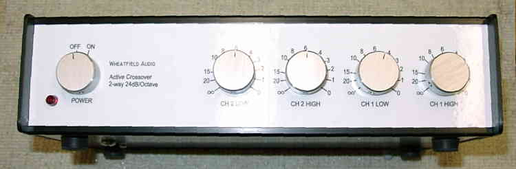
Front Panel
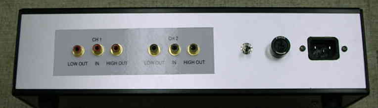
Rear Panel
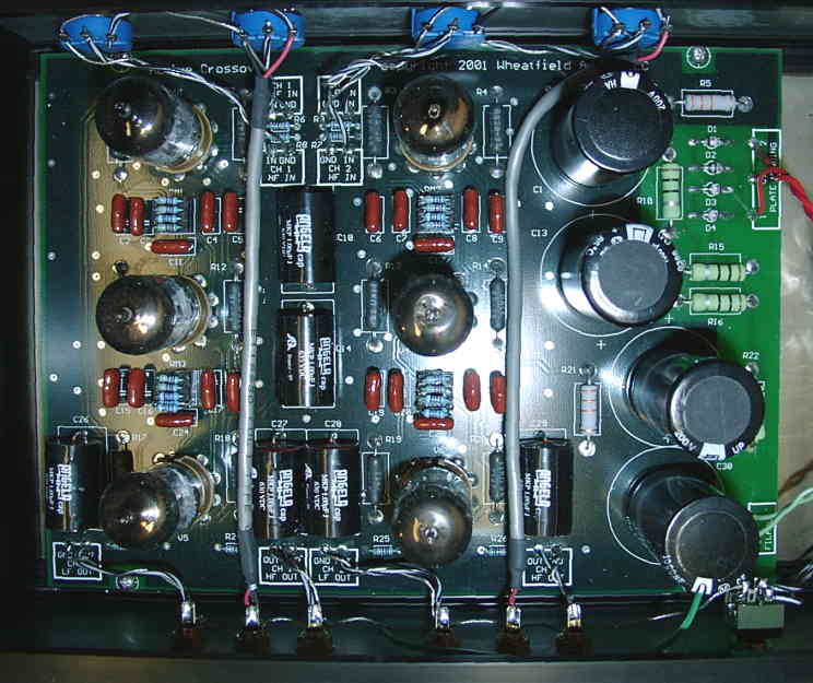
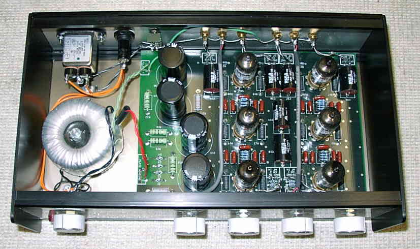
Detailed view of PCB in chassis
Notes on building your own crossover
As I mentioned above, the only technical area that I wasn't completely happy with in this prototype was it's noise performance. Part of the problem may have been that I got lazy and grounded all of the RCA jacks to the panel. If you build this, I would recommend using isolated RCA jacks.
You may also want to consider using a bigger chassis, and/or putting the power supply in a separate enclosure. There is definitely some coupling from the power transformer - it was much worse with an EI transformer, that's why you see a toroid in the picture. Also note that there is no connection between the filament winding and ground on the PCB. You will need to make this connection somewhere - I found that there was a large amount of noise induced if I let the filaments float. You might even want to consider DC filaments here to keep the noise down.
Total power required is +/-100V at about 120mA, and 6.3V at 1.8A (for 12AU7's). A Hammond 261G6 works fine for this, providing 250VCT at 144mA and 6.3V at 2A; but as I said above, you will need to move it farther away from the PCB than is possible in this enclosure. Note that there is virtually no DC current drawn from ground, so you can actually just use an isolated 200V supply, and let the bleeder resistors split ground. The toroid transformer I used has no center tap, so essentially this is the way I'm running it.
I used an enclosure from Sescom (model MC-25A) to house the crossover. You will find that the holes in my PCB don't exactly line up with the mounting in the enclosure, so if you edit the PCB you might want to check this out (I think they are 0.05" too close together, maybe more). Oops.
The PCB does not have any gain adjust controls on it. In fact, the PCB is laid out as four separate filters, two high-pass and two low-pass. To make a normal stereo crossover, you need to connect the input of a high-pass and a low-pass section together, to form the input. You can place a potentiometer at either the input or the output of the filter to adjust the gain. Putting it at the input is best for distortion (the input is attenuated first), the output best for noise (noise gets attenuated with the signal). I put the pots on the input.
PCB and design file downloads
If you have Eagle CAD, you can download the Eagle CAD schematic and PCB files, as well as the Gerber files (170kB ZIP archive) to modify or to fab a board. You have my permission to use these for non-commercial use as you see fit. See the commercial use notice above if you want to try and make a product out of it. If you modify them please remove the copyright statement.