LR phono preamp from ETF.13 (solid-state, with no caps in the phono EQ netowrk)
At ETF.13 (European Triode Festival) we held a shootout of LR phono preamps - that is, phono preamps that did not use any capacitors in the phono EQ section.
For details on the design process and how this circuit works, please read the presentation from ETF.13 (PDF or PPT).
For the shootout, I designed and built a solid-state preamp.
Recently, after listening to it compared to a couple of different tube and hybrid preamps (some of which I designed), I came to the conclusion that the solid-state LR unit sounded better than the others. I've also had a couple of requests to sell PCBs so that the design can be duplicated. So, I did some re-design to make it a little more DIY-friendly.
The PCBs will be for sale in my eBay store.
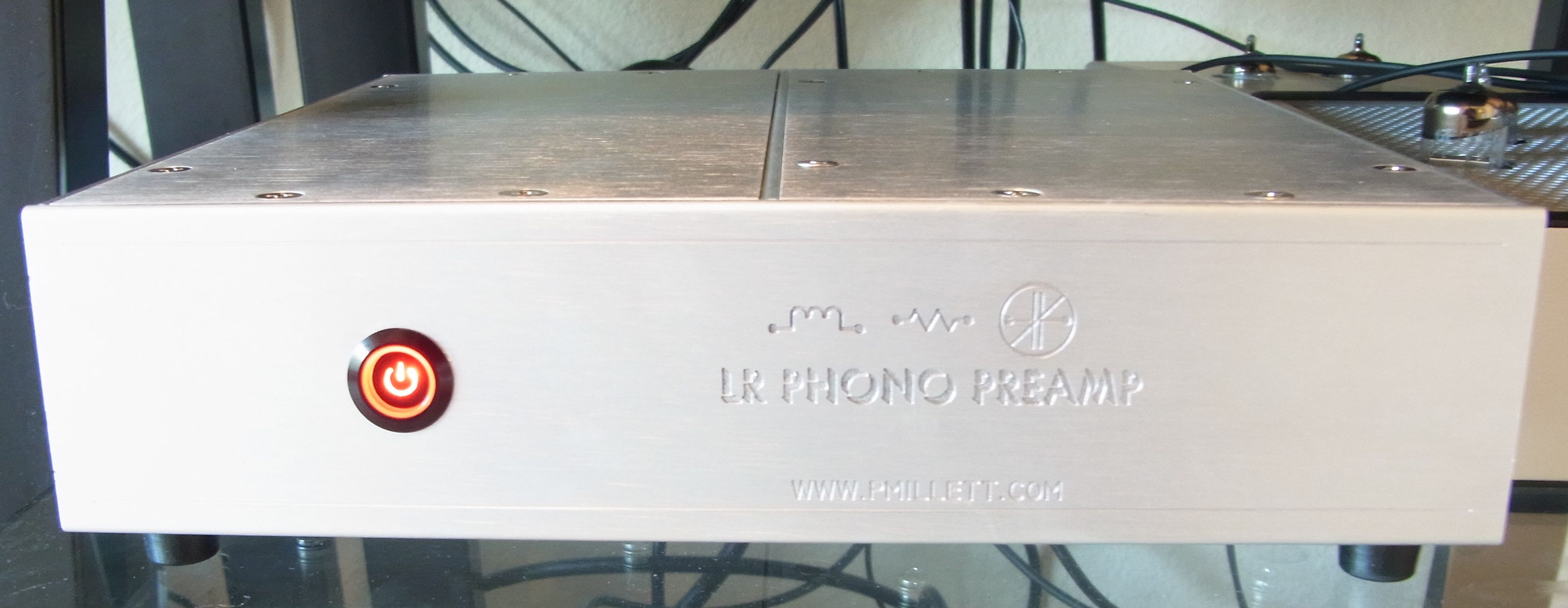
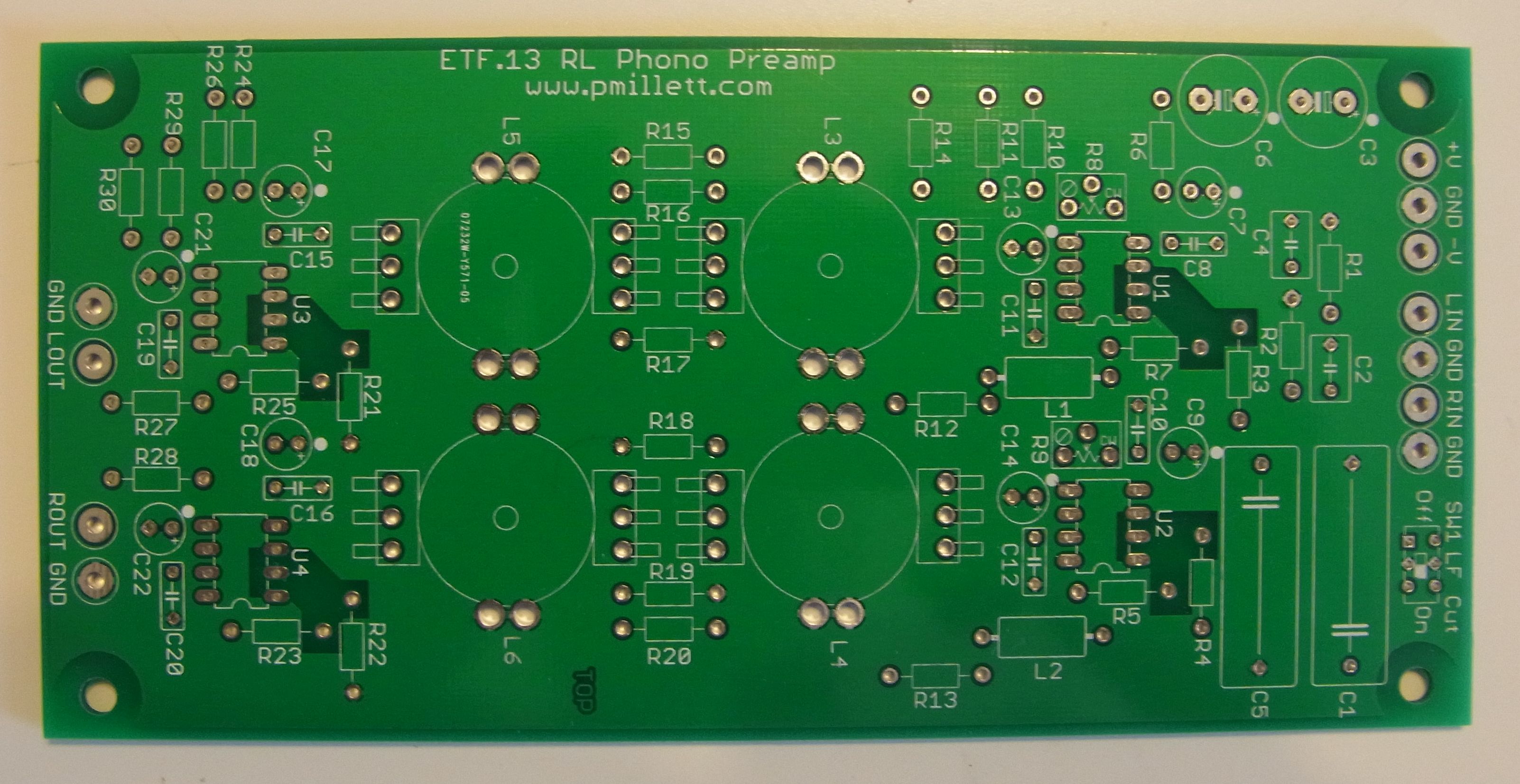
Here is the result!
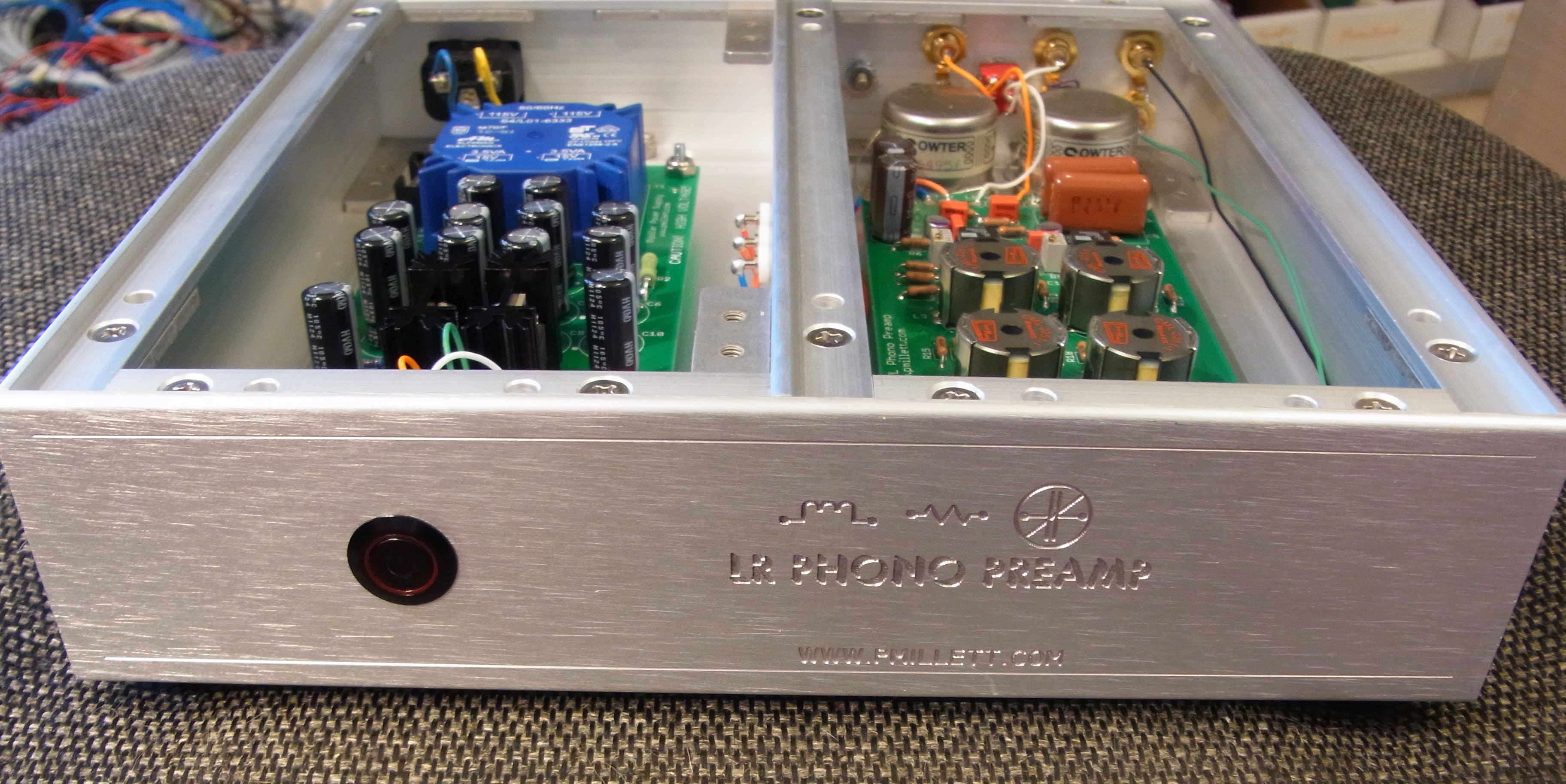
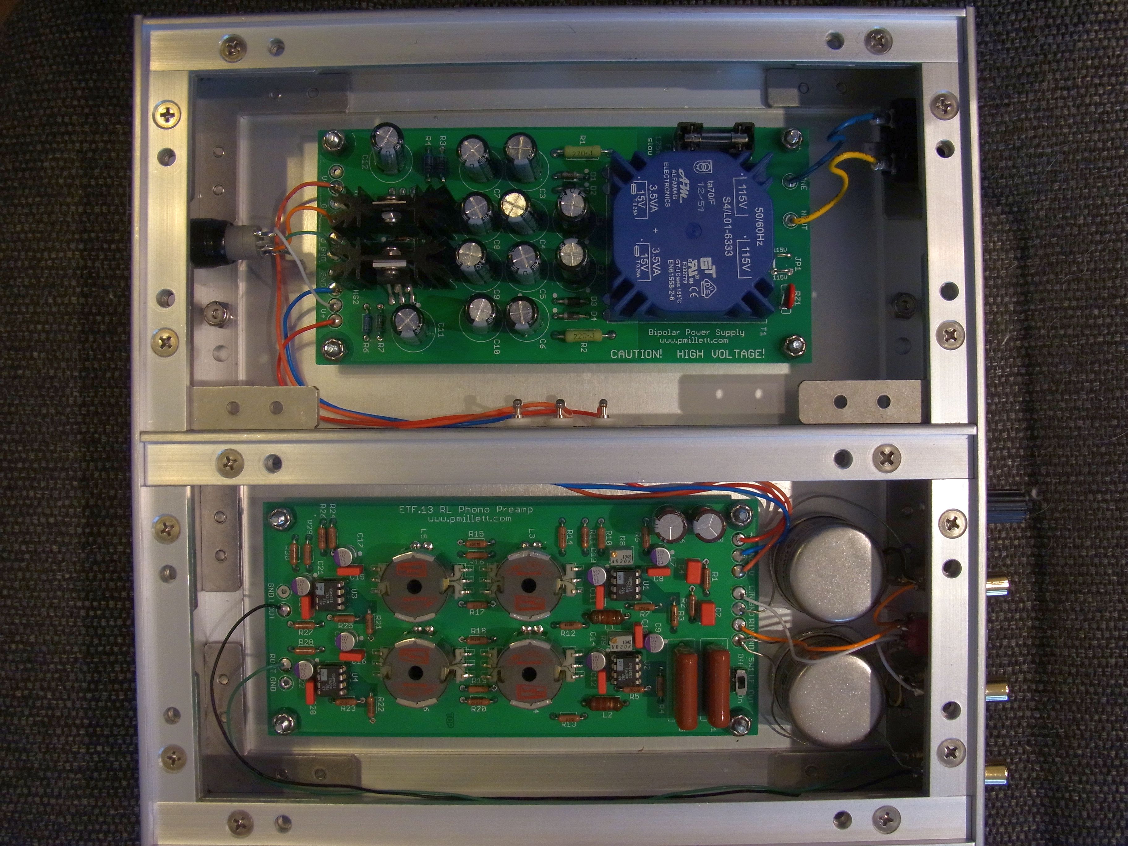
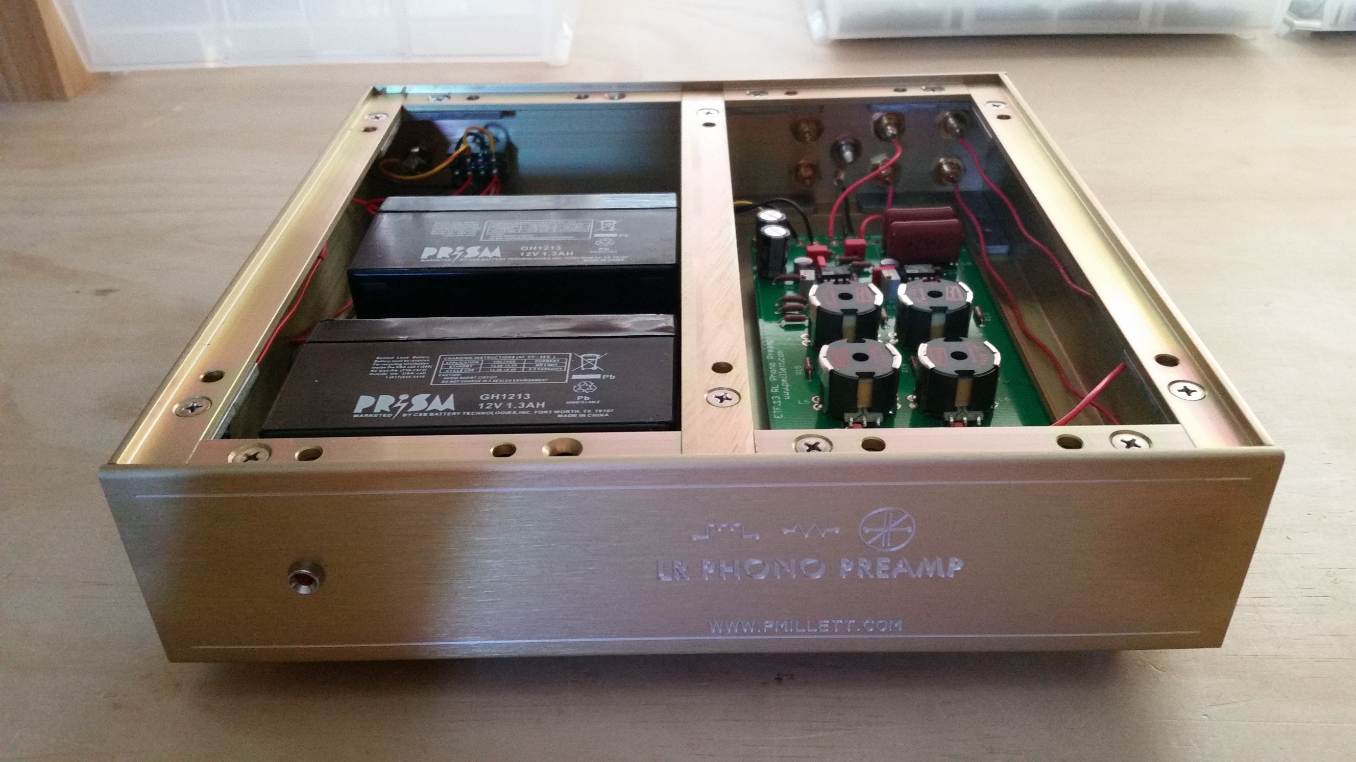
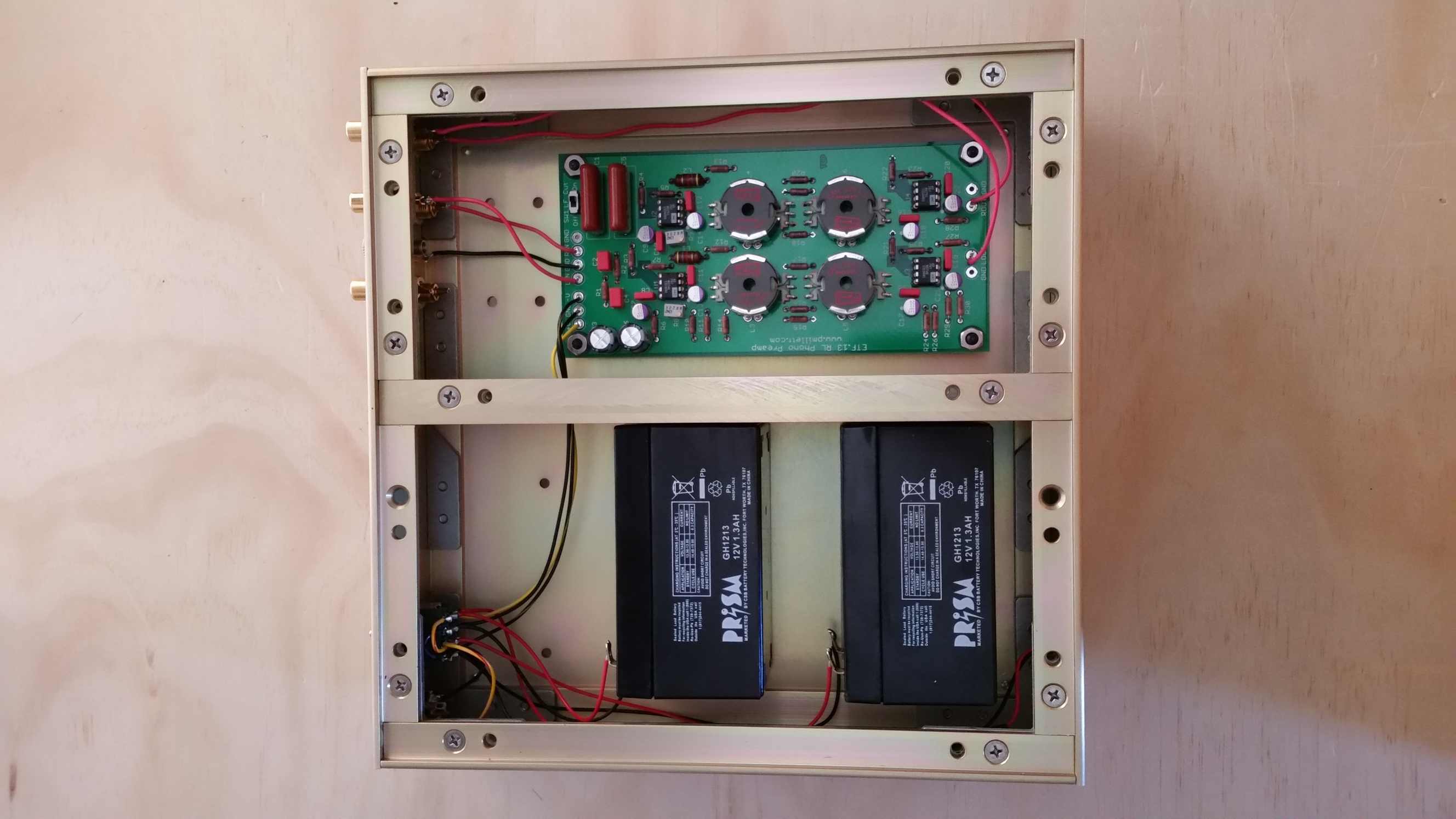
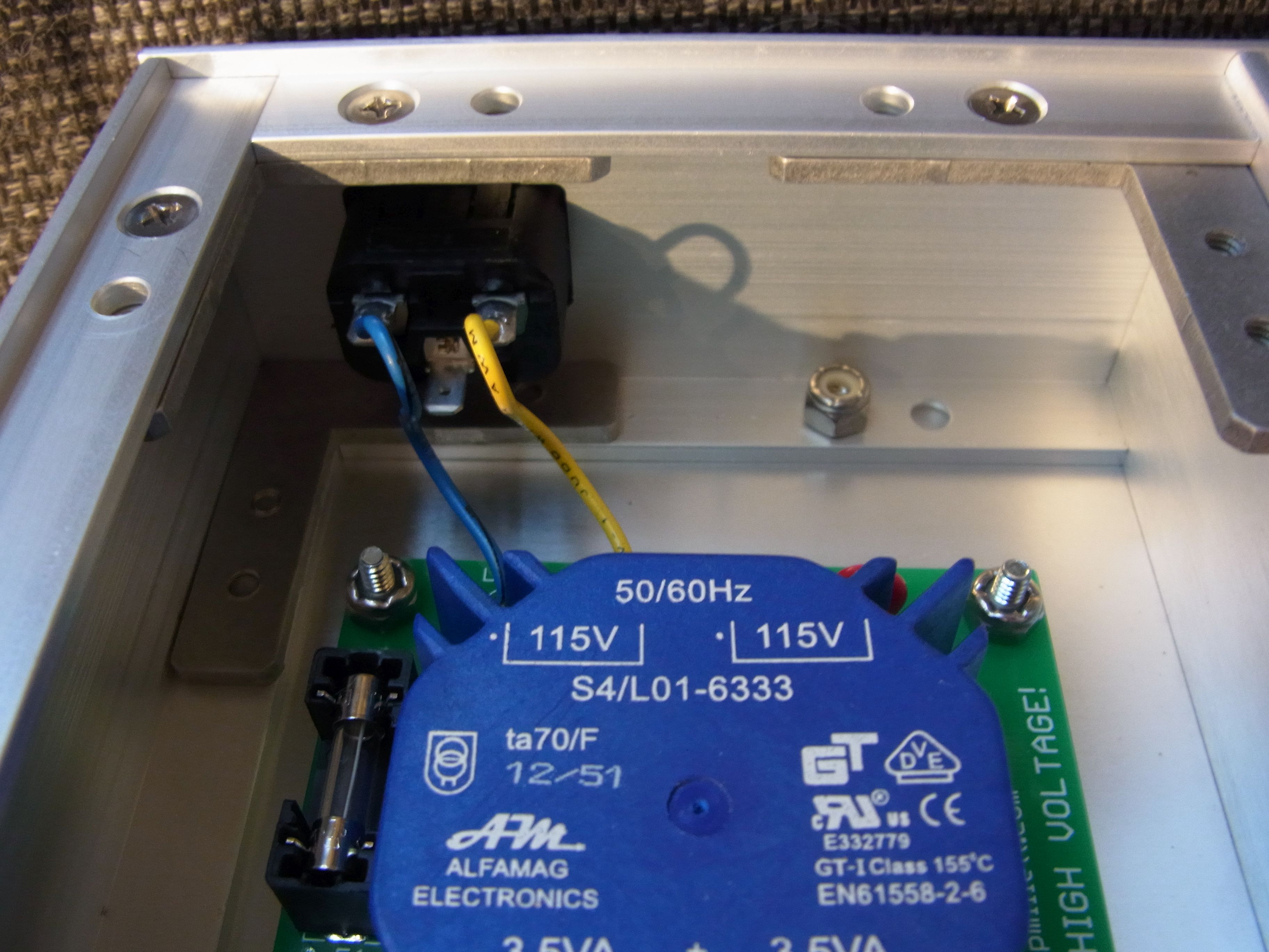
I removed the power supply and connectors from the preamp PCB, to allow DIYers to do things their own way. I also designed a companion PCB to implement a small opamp power supply (+/- 15V @ 5 watts or so). For my unit, I had Landfall Systems make me a "split" chassis, with two isolated compartments to contain the power supply and the preamp.
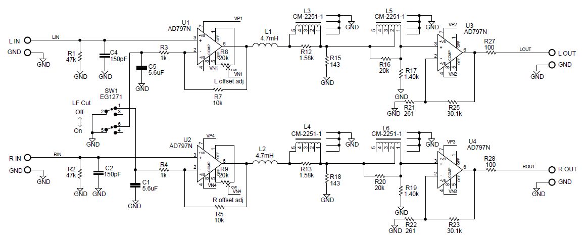
Here is what the schematic looks like (download the full schematic in PDF form):
Again, for a full explanation of the design, read the presentation (PDF or PPT).
Here is the parts list (BOM) in PDF or XLS form.
Dave at Landfall built a version using two sealed lead-acid batteries to get +/-12V instead of the power supply. It should run something like 40-50 hours on a charge. That's one way to ensure you have no power supply noise!

A couple of notes:
The EQ inductors are critical to the performance of the design, and many other components were tweaked to get the right frequency response. They are made by Cinemag. If you use something else you will need to change the resistors to get the right FR.
Since there is a large DC gain, I added trimpots to let you null the output DC offset. Adjust the pots (R8 and R9) to get zero volts DC on the outputs with no input signal.
I included the ability to add a LF cutoff around 20Hz. If you don;t want it just jumper C1 and C5 and leave the switch out.
The PCB is 3" x 6.25". You can download a mechanical drawing with mounting dimensions it here.
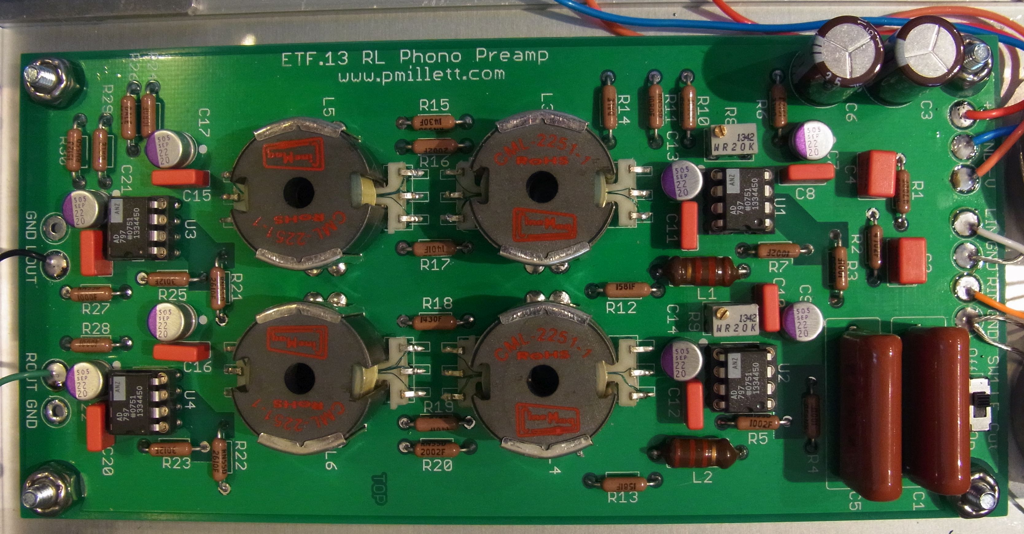
Note the orientation of the inductors in the photo - it is not obvious from the PCB or inductors!
The performance of the preamp is pretty good. Frequency response tracks RIAA within +/-1dB:
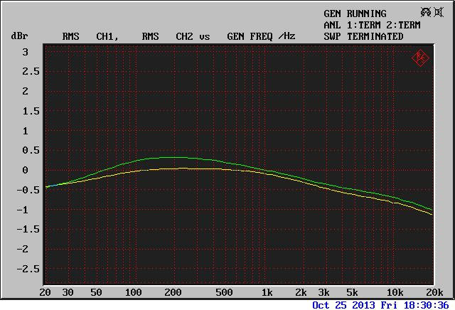
For more performance details, see the ETF presentation.
The preamp uses about 40-50mA at +/- 10-15V. I used an AC power supply, but you can also power it from batteries. Dave at Landfall built a version using two 12V sealed lead-acid batteries...
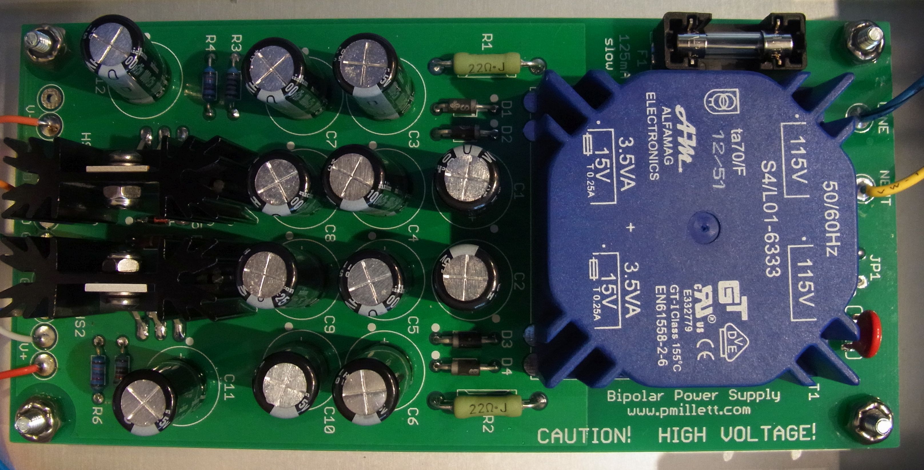
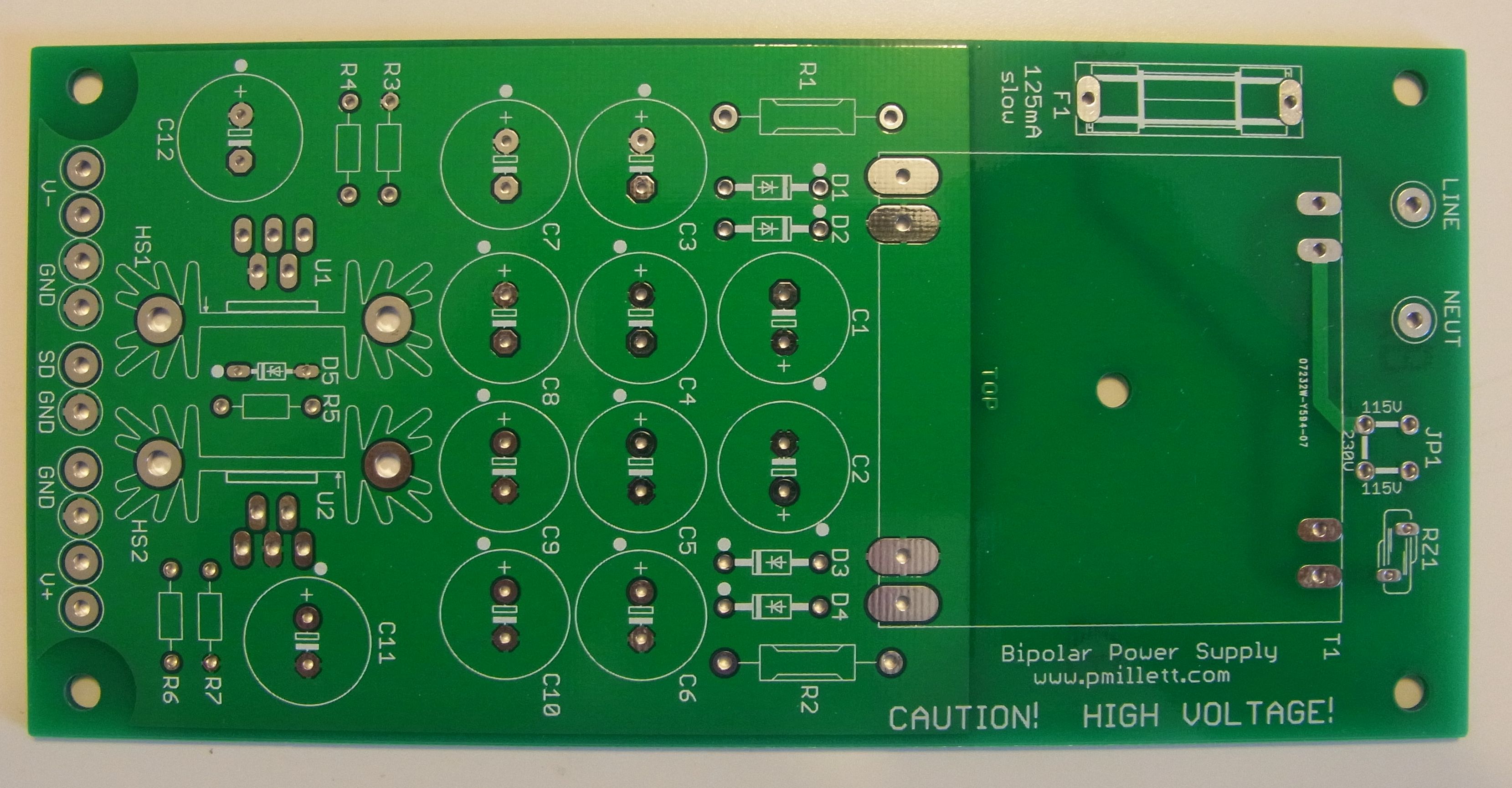
Here is the power supply (download a PDF schematic):
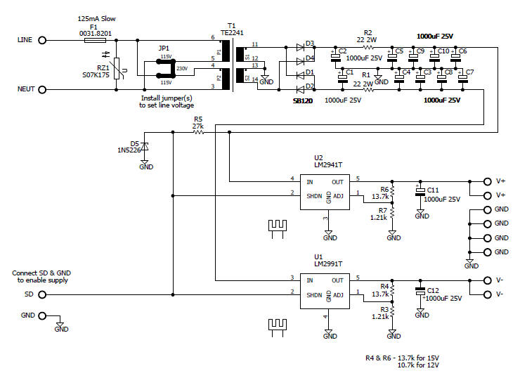
The PCB is the same size as the preamp. Download a dimensioned mechanical drawing in PDF, and the parts list (BOM) in PDF or XLS
Some more details about how I built this...
I broke a lot of rules, many of them my own, building this preamp.
The first thing you might notice is that I did NOT ground the chassis to the mains ground! Yes, this is potentially dangerous, and I don't recommend that you do it this way! For safety, it is always best to connect the chassis to the AC mains ground. That way, if there is ever a short between the AC line and the chassis, it will trip the breaker and not energize the chassis.
That said... since this is a low-voltage design, the only hazardous voltage is the AC line connection itself. The transformer used here qualifies as "reinforced" insulation, so the secondary side is safe. The only risk is a short from the AC line to the chassis. To me this is a manageable risk so I decided to not ground the chassis.
I recommend that you DO NOT DO THIS... if you do, you need to understand and accept the risks! As my Dad used to tell me all the time when I was a kid, DO AS I SAY, NOT AS I DO!
By the way, part of the reason I did this - and why I do not have an EMI filter or filtered IEC connector - is that in some cases the AC mains ground connection in a preamp can generate a ground loop that makes things noisy. And also because I wanted the chassis to be grounded to signal ground:
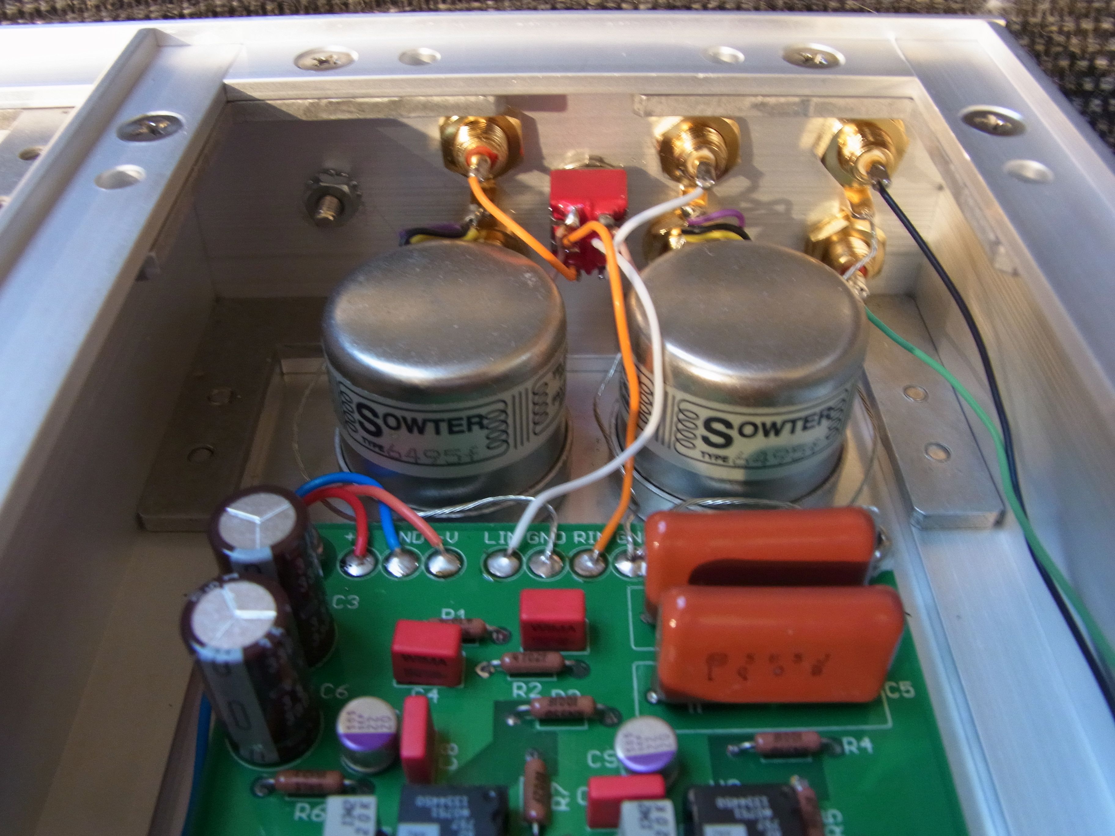
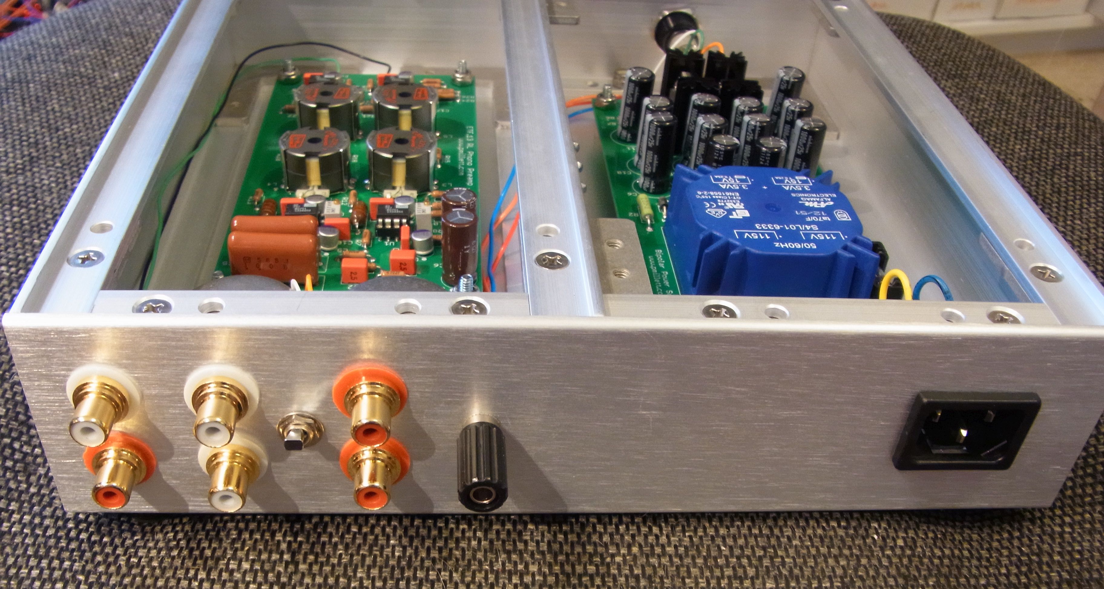
Yes, all the RCA connectors are connected directly to the chassis without insulation! Another rule broken. Just like in the olden days, the chassis here is ground. It is also plated with clear chromate, not anodized, so it is all very conductive.
A toggle switch on the back panel selects either direct inputs for a MM cartridge, or the output of a pair of Sowter MC step-up transformers for a MC cartridge.
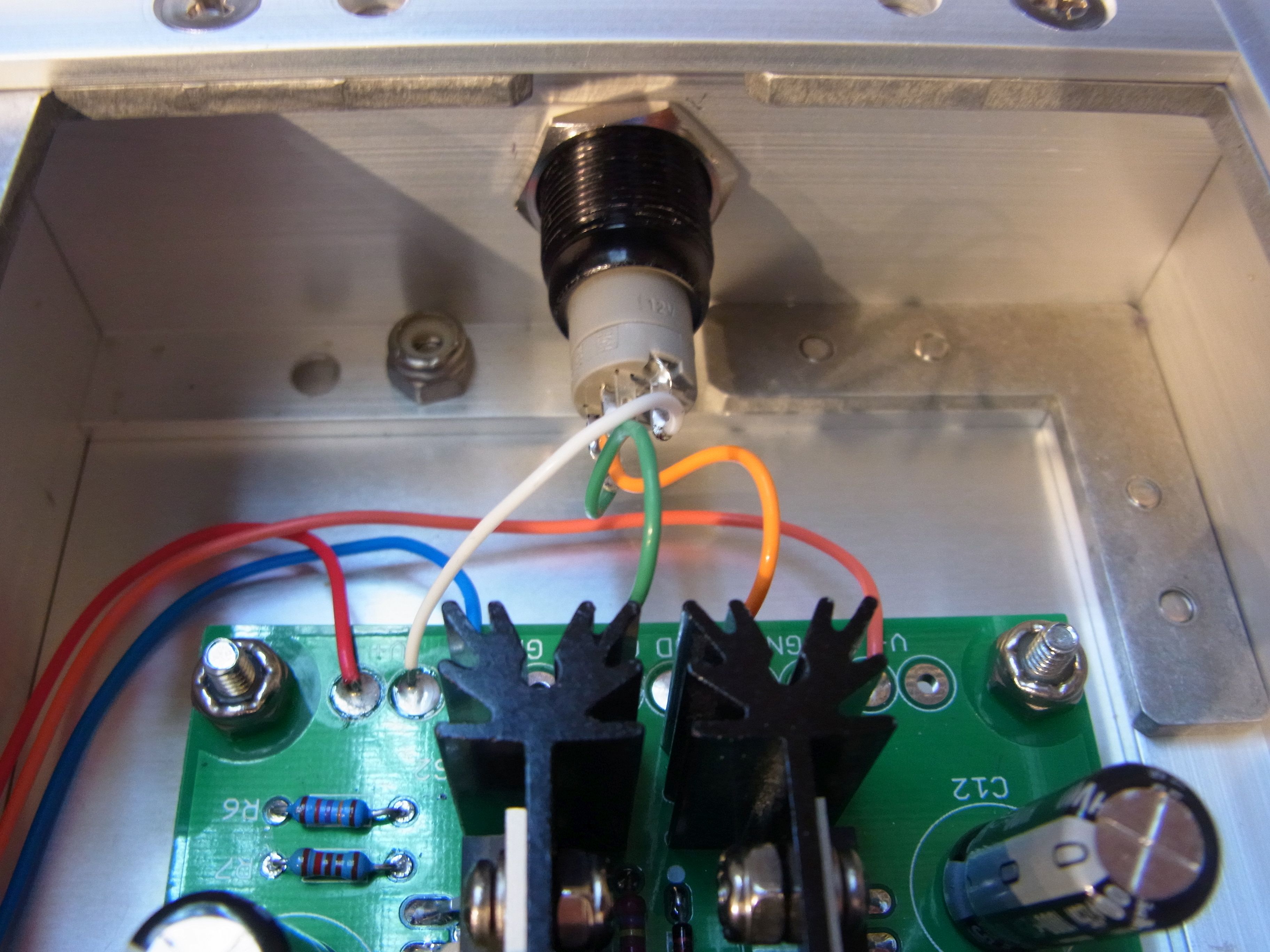
The power supply does not have a switch in series with the AC line. I used the shutdown function of the voltage regulator ICs to provide a power on/off (actually on/standby) function. To enable the supply, you short the "SD" pad on the PCB to GND. I used an illuminated push switch from eBay to do this. The LED is powered from +15V.