The "Engineer's Amplifier" 50 watt monoblock
Update 6/15/18 - I made a version of this board without the tube sockets, so you can use whatever tubes you want.
This board is identical to the original, except that instead of having compactron sockets on the PCB, there is a big hole for the socket to be mounted directly to the chassis with wires connecting down to the PCB. That lets you use whatever tube you want.
Note that I also took the grid stopper resistors off the board - you can use them to connect between the PCB pads and the socket.
There is also a through hole that you can use to feed a wire from a plate cap down through the chassis and board. There are mounting holes located that match most tube sockets, so you can put a standoff there to support the PCB if you want.
Update 1/29/17 - I optimized the NFB components - C1 = 33pF, at least for the Hammond OPT. Also added a bunch of measurements (towards the bottom of the page).
(Note that the photos are hyperlinked to full-size photos in grisly detail)
I designed a 50 watt monoblock version of the Engineer's amp!
Here is the schematic (PDF file). Pretty much identical to the original, with slightly higher B+.
Here's the parts list (BOM) in .XLS or .PDF form. The BOM includes everything on and off the board, except for the chassis. The BOM cost (again minus chassis) is under $500 with Hammond transformers. Also, here is a link to a Mouser BOM. Please check it carefully, I am not responsible for errors!
I used the 6HJ5 sweep tube for the outputs. I am using 6GU5 tubes for the input/driver. Thanks for the idea George!
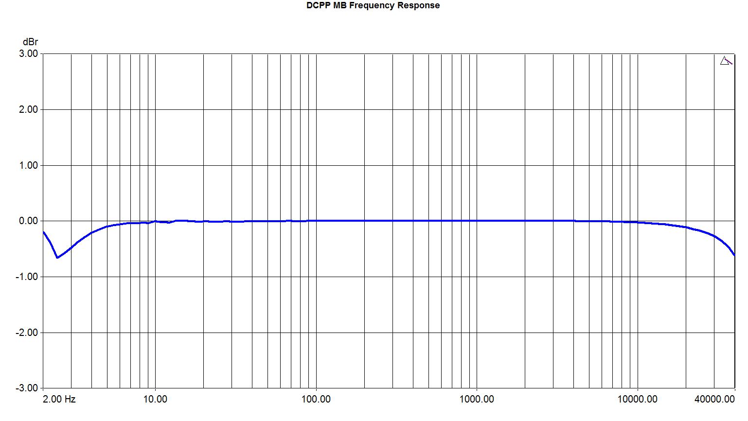
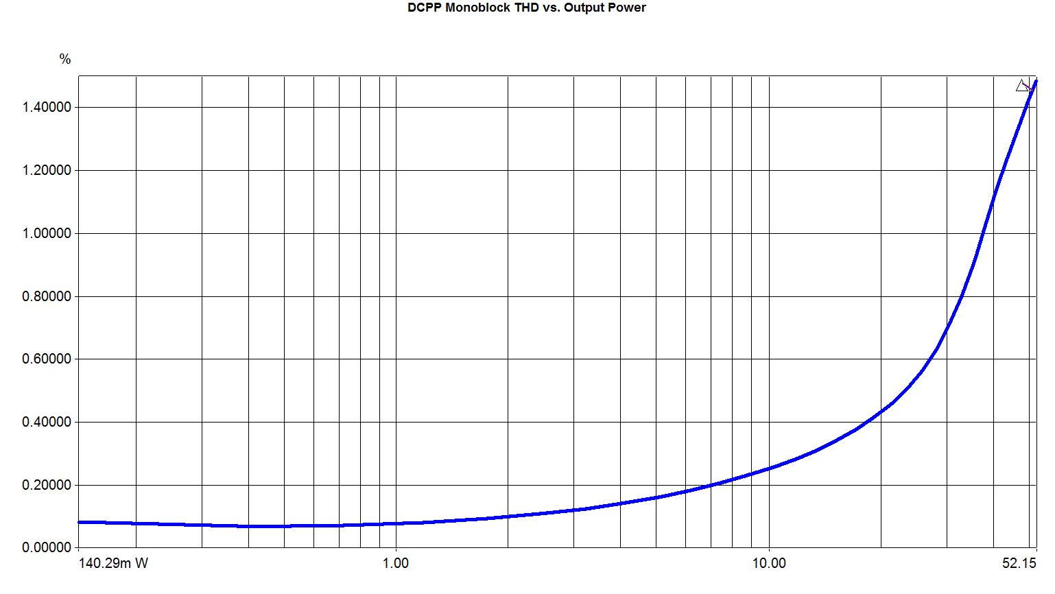
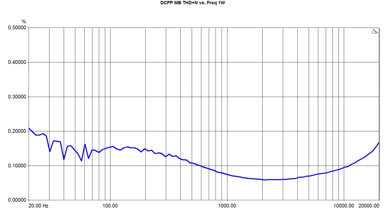
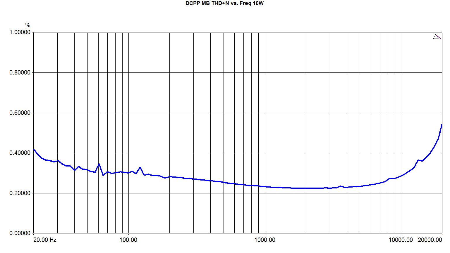
Modest loop NFB is used in addition to substantial plate-to-grid feedback, as in the original Engineers Amp. This gets you a bit over 50 watts into 8 ohms at 1.7% THD at 1.85V RMS in. About 0.1% THD at 1W, and about a 1 ohm Zout. FR is flat from ~10Hz to over 10kHz. I will post more measurements and graphs soon...
So far the amp looks unconditionally stable, with no load, heavy load, etc. but I need to do some more testing.
The chassis was made by Landfall Systems. They can build one for you as well. I highly recommend it, unless you really enjoy doing metalwork.
In that case, you can download the mechanical CAD files (AutoCAD DWG and DXF files).
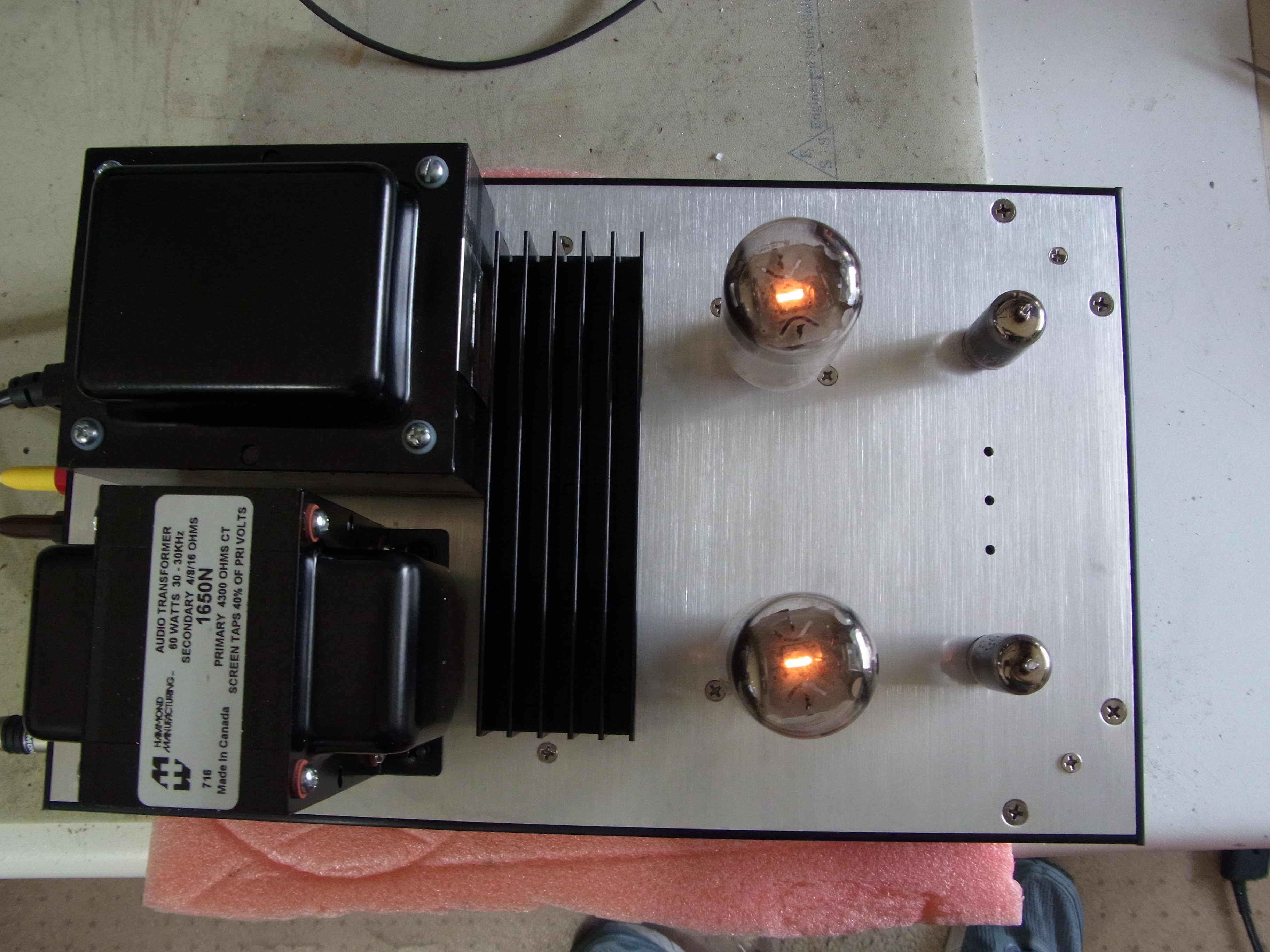
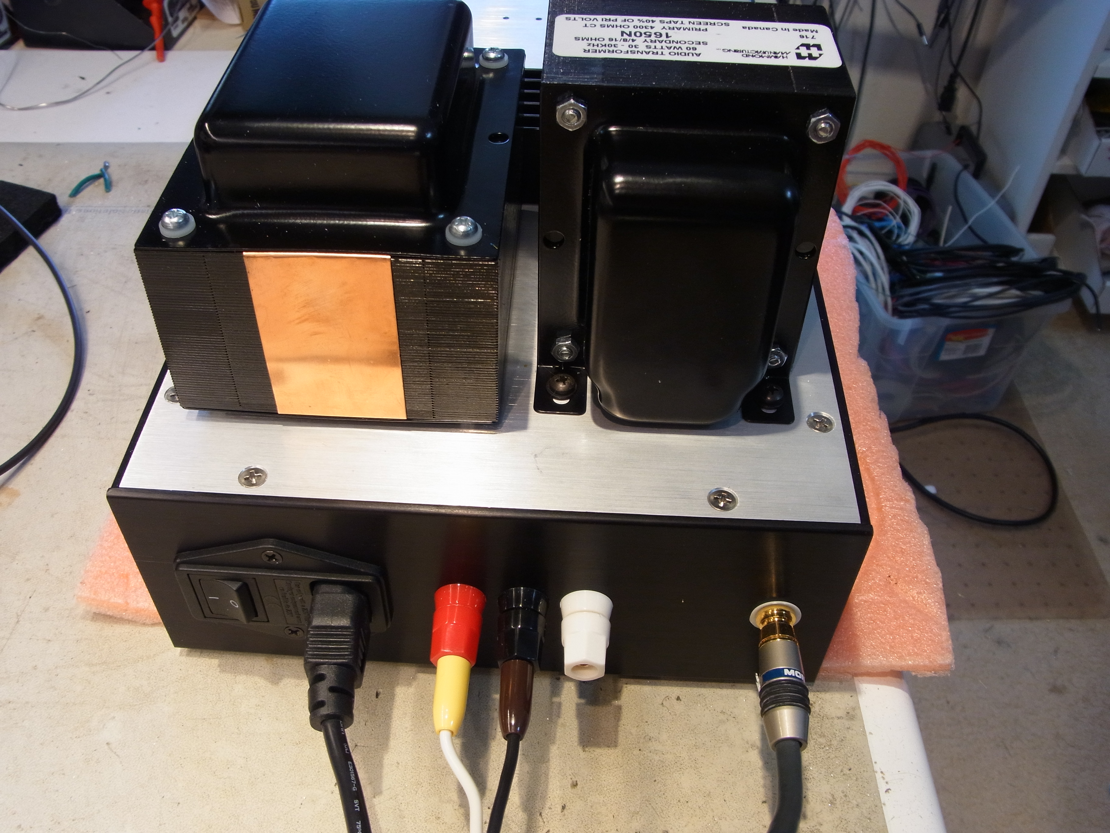
I wanted to keep the deign economical, so no fancy parts are used. The power transformer is a guitar amp (Fender 100W) transformer, Hammond 290FX or similar from the guitar amp winders. Relatively cheap and readily available. The OPT is a plain ole' Hammond 1650N. Of course, you could use Edcor or something else.
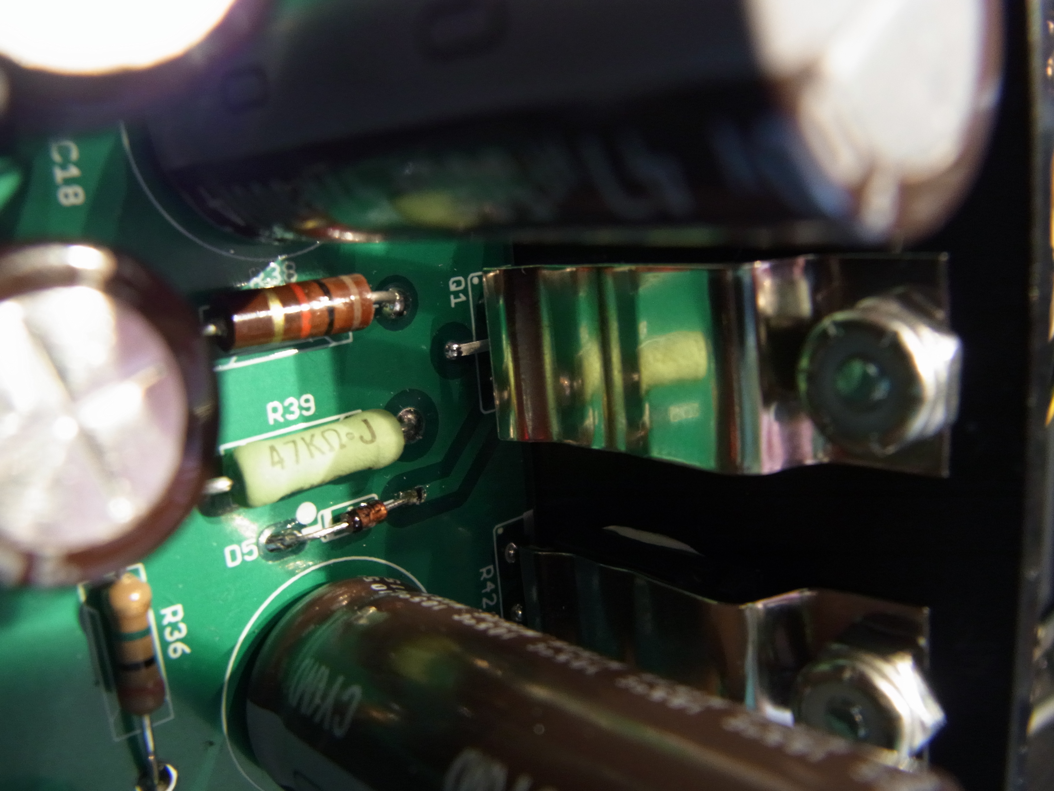
Here's a view inside:
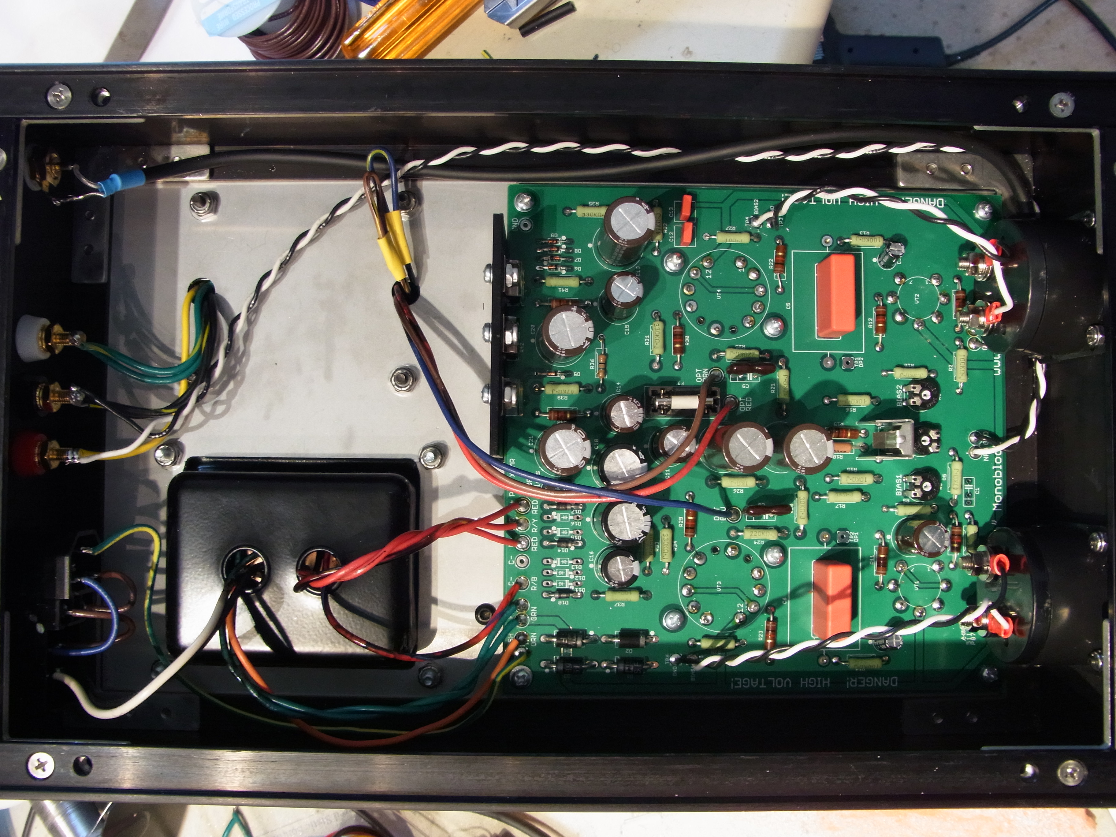
At the top edge of the PCB you can see the power MOSFETs, and a series resistor in a TO-220 case, mounted to a black aluminum angle. The angle passes through the chassis top and is bolted to a heatsink extrusion. This is to heatsink the ripple filter and dropping resistor and FET for the screen grid supply.
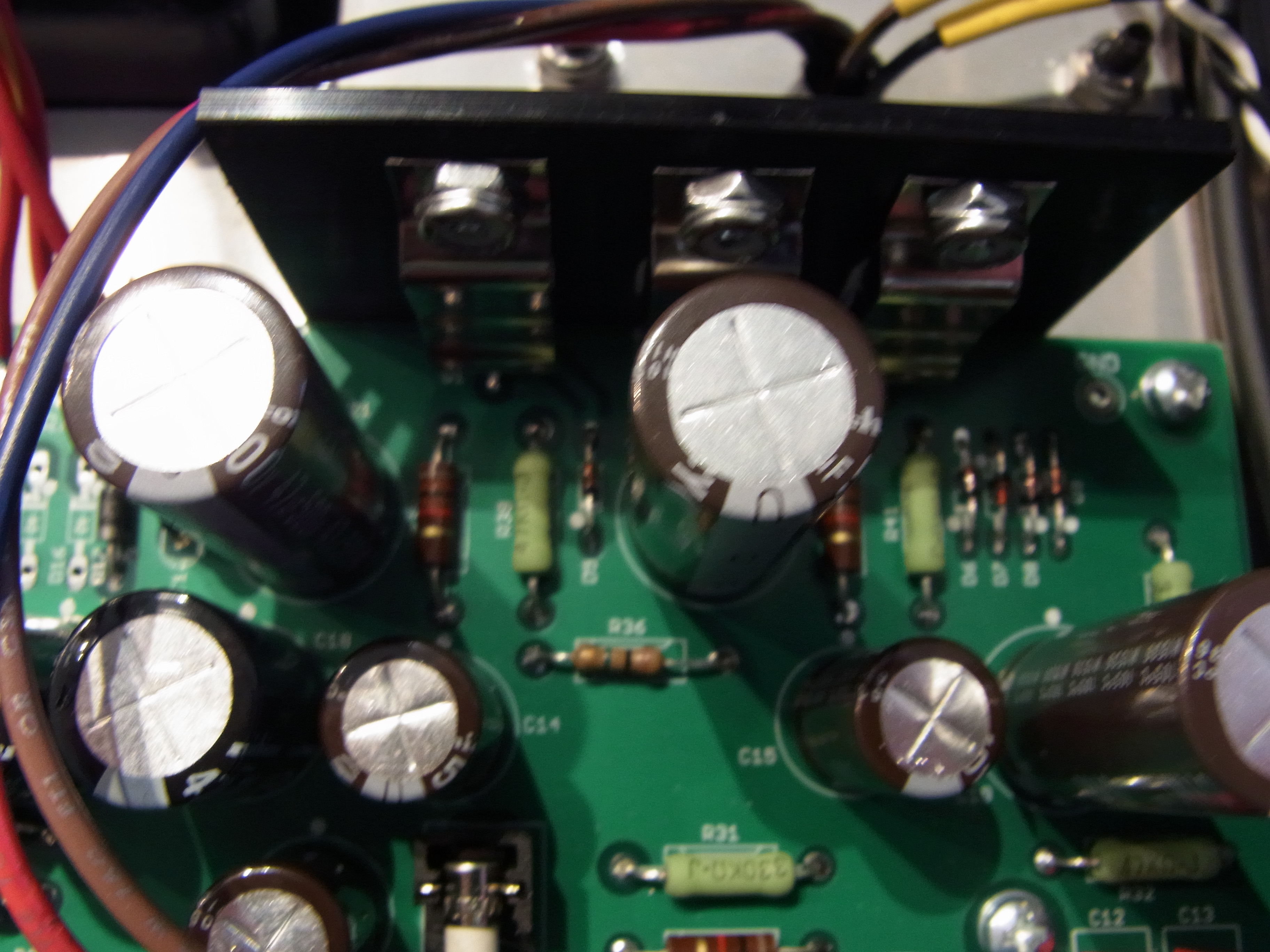
The FETs are held to the extrusion using spring clamps. This prevents you from having to precisely line everything up. It's still a bit of a pain to put together, though. the clips come from Aavid, part number MAX07NG. You can get them from Mouser or Digi-Key. Do not forget to use thermal grease or thermal pads between the case and heatsink! And if you use MOSFETs with a metal tab, they MUST be properly insulated form the heatsink!
I like to put meters on amps with fixed bias, so I got some inexpensive Chinese meters off of eBay... 1V = 100mA cathode current. You can access the bias pots through those little holes you see in between the driver tubes. The middle pot is driver balance. I actually didn't see much need to adjust it...
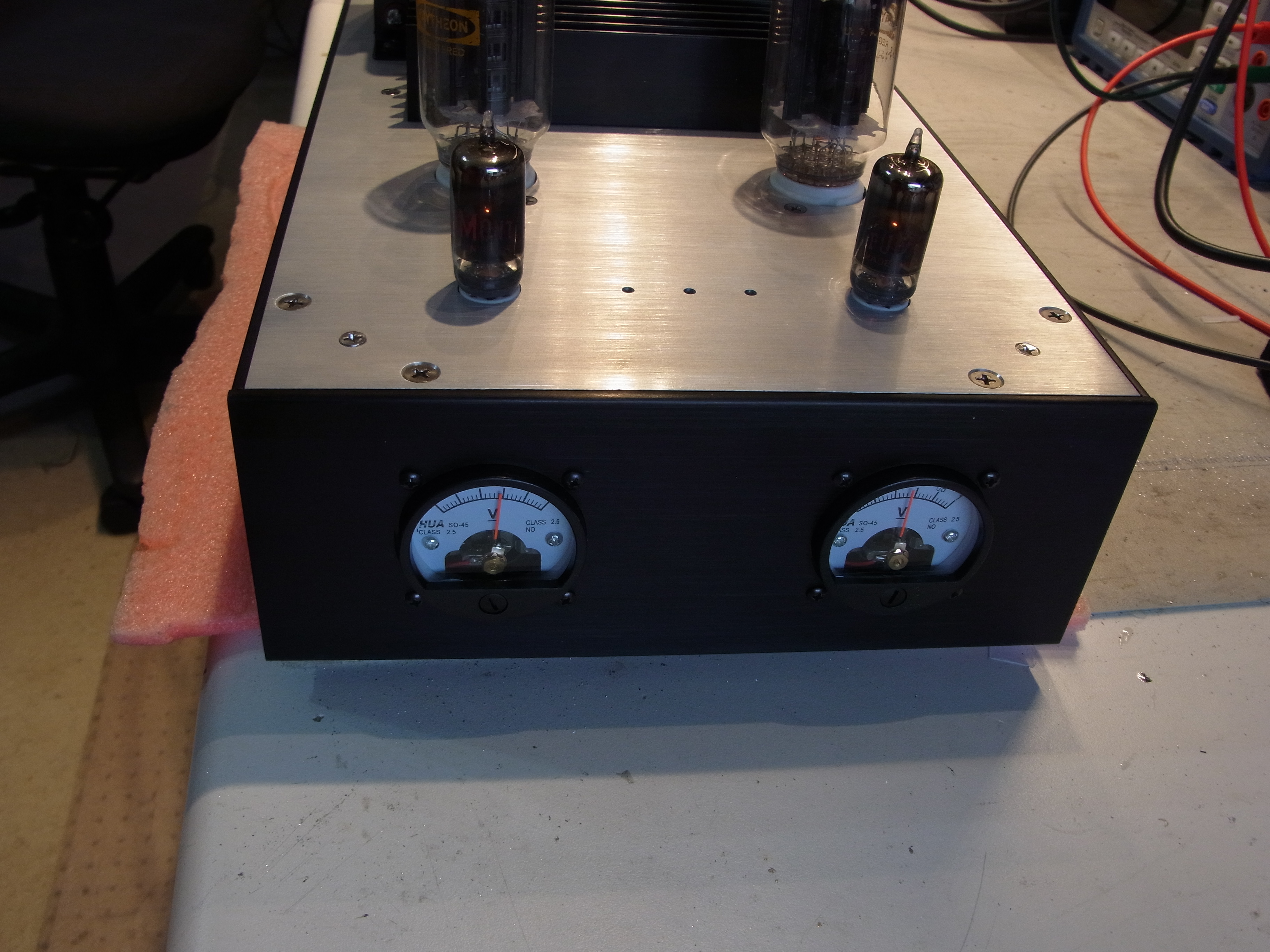
It's a little snug up front but everything does fit :)

4 and 8 ohm taps wired out the back.
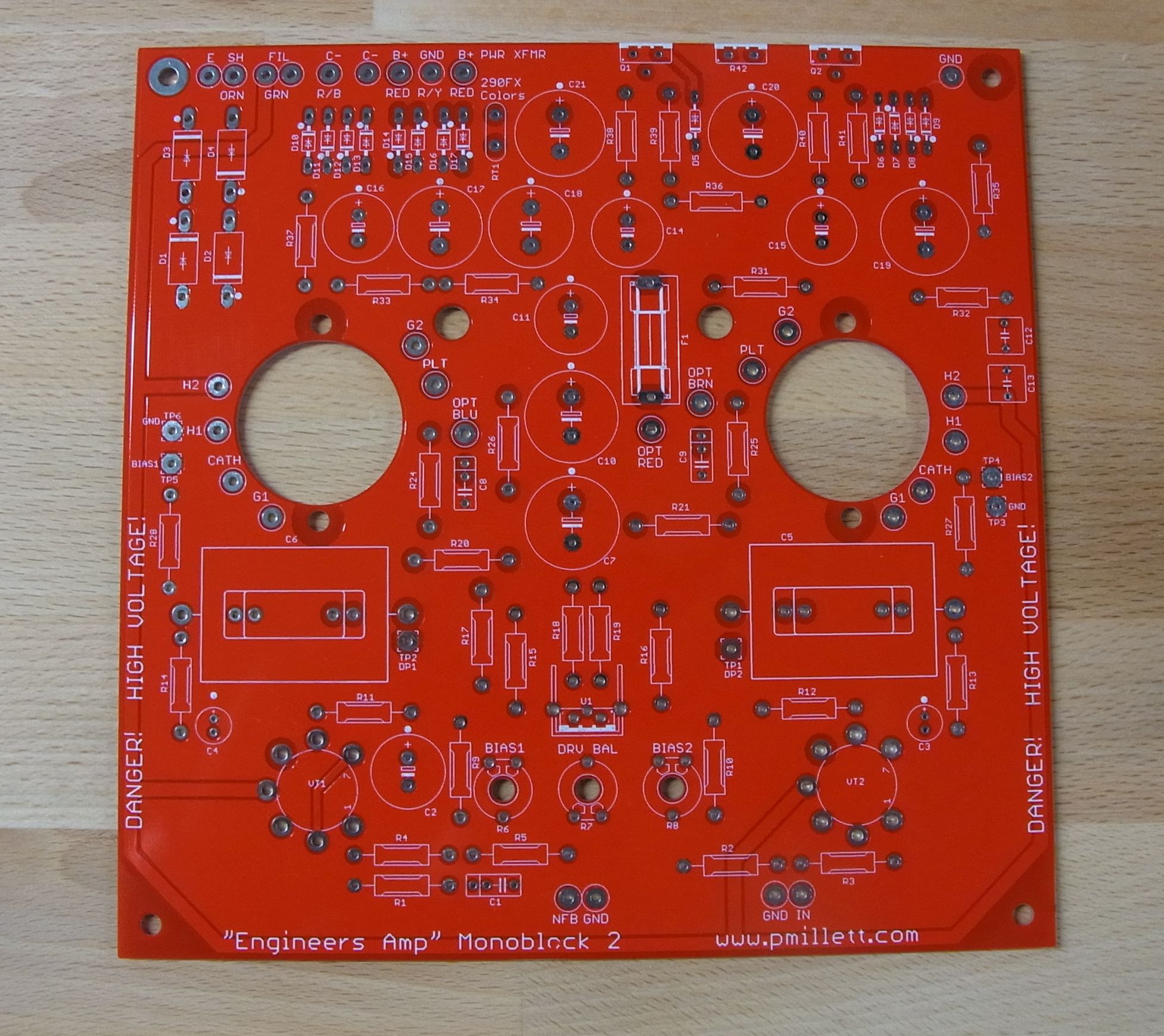
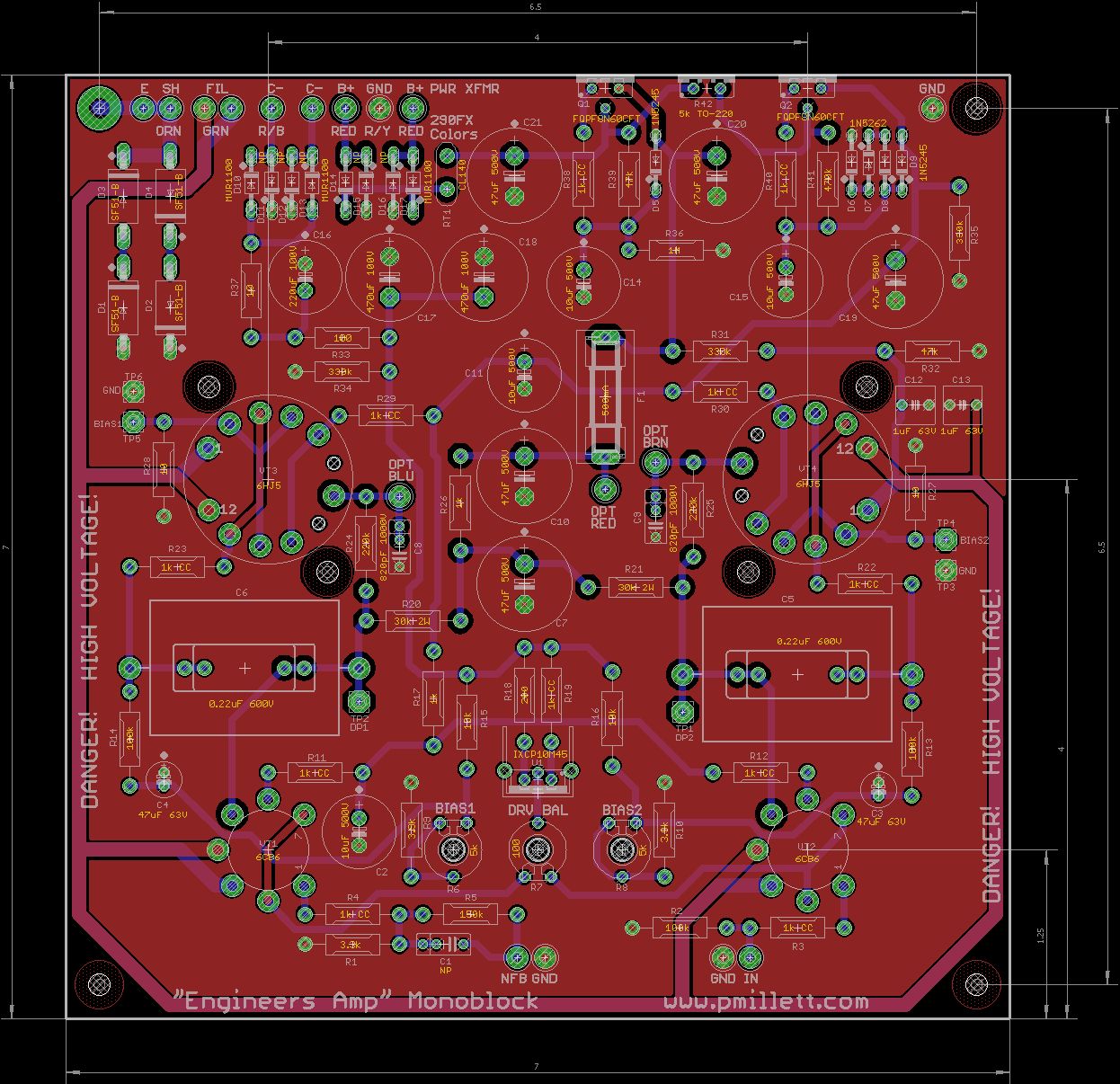
Here is the assembled prototype PCB. Pretty straightforward assembly. Here you can see the two power MOSFETs and one TO-220 power resistor I talked about above.

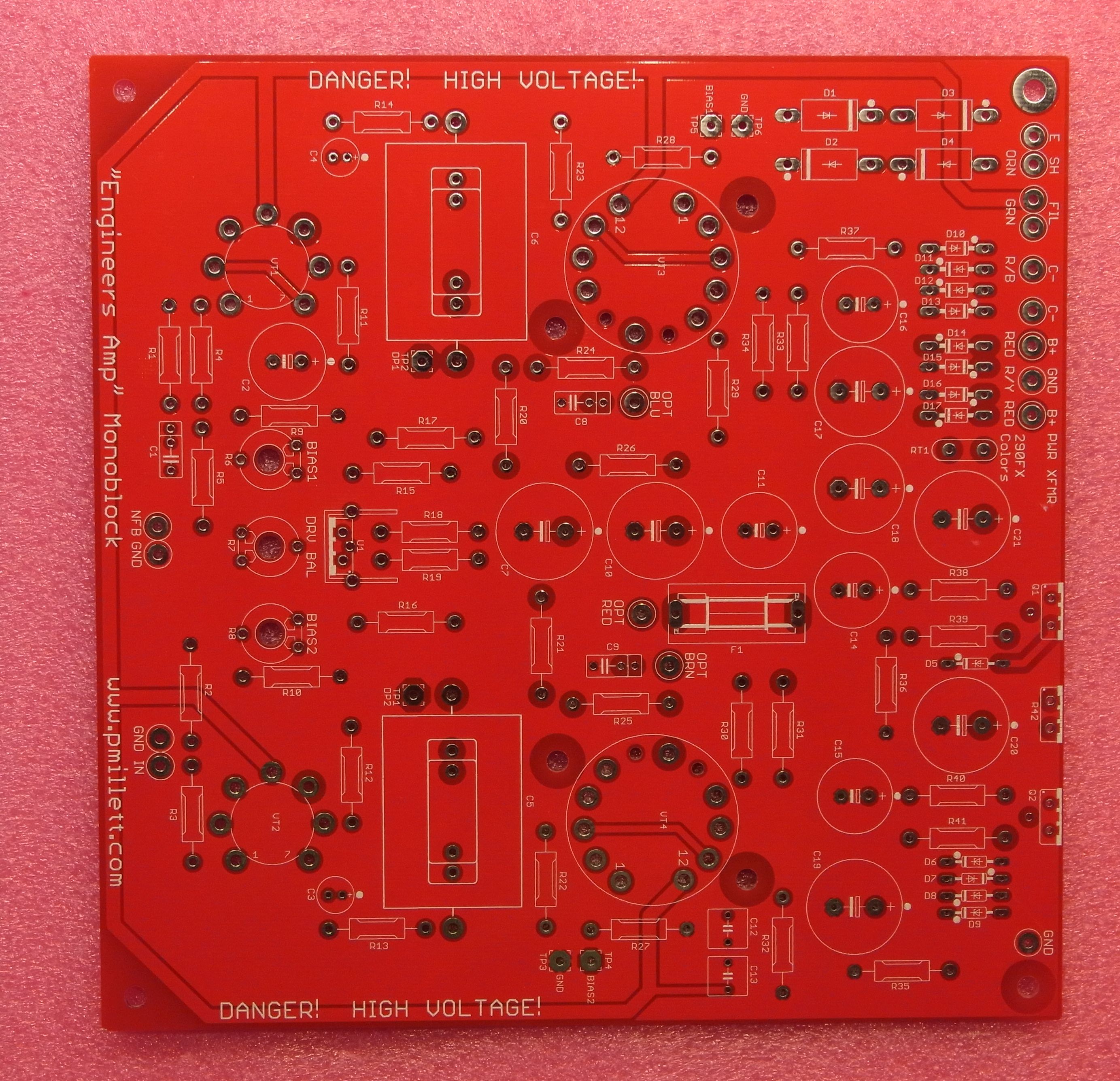
Here is the prototype flipped upside down for testing:

It is a small 7" x 7" PCB. I made a bunch so will list them on eBay. The real ones are red (of course) instead of green like the prototype.
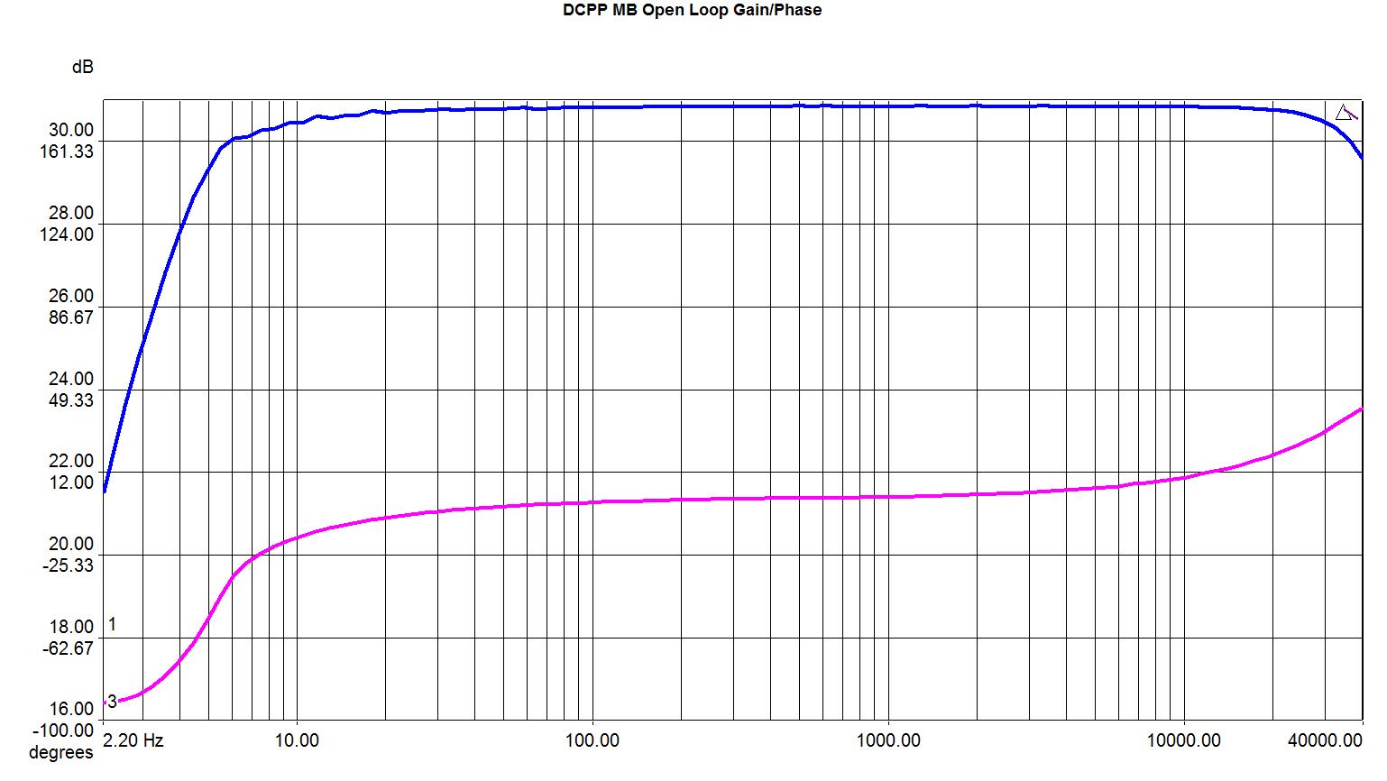
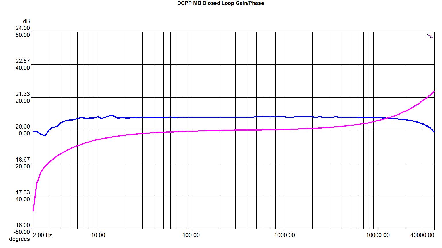
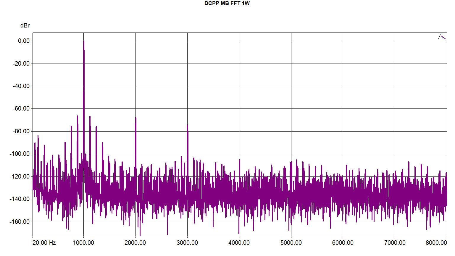
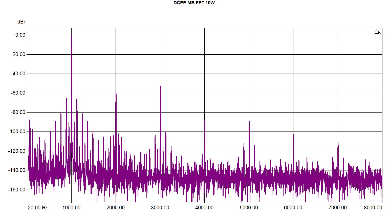
Here are some measurements. Please ignore some of the bumbp ploits at LF, I'm still learning to use my new audio analyzer :)