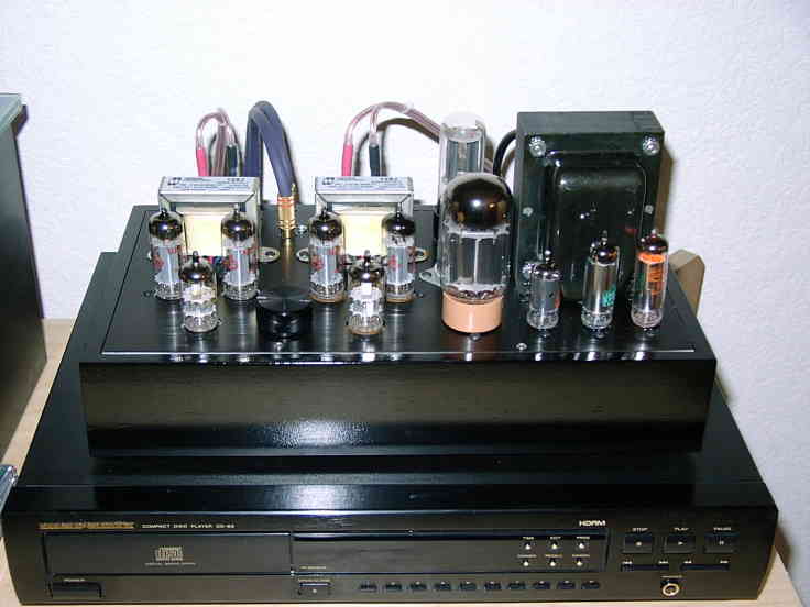
7044 push-pull amp
OK, I admit I more-or-less stole this idea from Bob Danielak's 5687 amp...
Having a bunch of 7044 computer triodes laying around (a lot like a 5687, also 7119/E182CC), and a couple of Hammond 125J's I bough for the EL34 SRPP project, I thought I'd throw together something useful out of them.
Unlike Bob's amp, I used 6922's as drivers, in a configuration with a grounded cathode stage driving a split-load phase splitter, which drives the 7044's (two triodes paralleled). The gain worked out just right.
This amp has very low distortion... to a point. Mostly third harmonic, which isn't really ideal, but it is push-pull. I guess the single-ended driver contributes very little to the distortion.
With the Hammond 125J's I only get about 2-3 watts out of this puppy before the transformers start to distort. Seems like you should be able to get at least 5-6 watts with a better transformer. But I'm using it to drive some TQWP's with Fostex's in them, and 2W is more than enough.
The other unique (?) thing about this amp is the power supply. Since I have more tubes than sense, instead of bothering to go out and get a filter choke for the power supply, I just made a tube regulator instead. I also got by with very little capacitance, 40uF cap input filter plus another 20 on the regulator output, from a multi-section can I had laying around. The regulator is the "usual" circuit, using a 6AS7 or 5998 (the cool-looking pink base tube in front is a GE 5998A) pass tube, 6AU6 error amp, and an 0C2 and 0A2 for reference and screen grid. The 75V 0C2 really lights up bright!.
The amp sounds good, though almost a tad on the solid-state side! Maybe the 6922's.... I'm really a 6SN7 man myself.
Here's a picture of the inside of the amp. I used a small piece of PC board material to make a ground plane. This worked really nicely, and I could just solder down a terminal strip where I needed to, without drilling any holes.
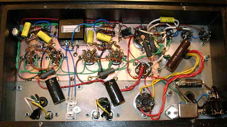
The input tubes are at the top of this picture, on either side of the black volume control pot. The VR tubes are in the upper right, rectifier at the bottom, with the can cap above it and the pass tube above that.
Here is the schematic (2 pages, 53kb PDF file)