Sangaku DIY nutube Headphone Amp / Preamp
NEW: I have revised the PCB to fix the error on the R2 PCBs. The R3 PCB shipping now is GREEN.
There is an error in the old (black) Sangaku DIY rev 2 PCB. The mistake causes a small DC offset in the unbalanced and preamp outputs. It can be fixed in a couple of different ways. Please read these instructions to correct the error. Sorry!
I was asked about making a DIY version of the Apex HiFi Sangaku, which is discontinued.

The Sangaku was a hybrid headphone amp / preamp, using the Korg nutube as a single-ended voltage amplifier, with balanced in and out. It used mostly surface mount components.
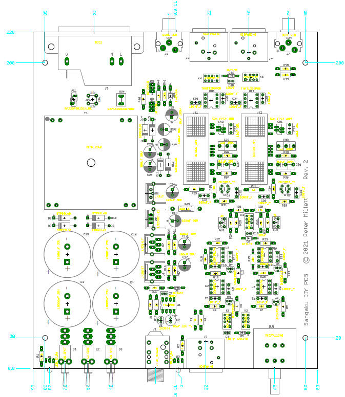
So... long story short I re-designed it to make it DIY friendly. That meant simplifying it a bit, changing to all through hole parts, and removing the fancy microprocessor-controlled front panel. Here is the result:
It retains the basic architecture of the original. A THAT line receiver sits in the front end, driving the nutube grid at zero bias. About 75V is used as a B+ voltage and two nutubes are used, one for each channel with the triodes connected in parallel. Opamp buffers complete the signal chain to drive the headphones and the line out.
Here's the schematic (or download the whole thing in PDF form):


It is implemented on a single PCB (the R3 rev that fixed the offset issue is green, the protos were blue) (download a PDF):

Here is a parts list (BOM) in .XLS or .PDF format. Most of the parts can be had at Digi-Key or Mouser. I sell the nutubes and PCB on my eBay store. The board will fit into a standard Hammond extruded enclosure, 1455U2201BK, or in whatever you'd like. The front and rear panels were made by Landfall Systems - they can make them for you as well, and I may wind up keeping some in inventory to sell.
If you are at all familiar with the nutube, you no doubt have heard that it is very microphonic. Well, yes it is. When I first built this there was a terrible "ping" whenever I flipped any of the switches. So I came up with a vibration mount that can be fit into the same PCBs that the nutube was designed for:
It uses a custom flex circuit and a partially populated header to connect the flex into the main PCB. Then, the nutube is mounted to the PCB using adhesive tape on some very soft foam.
This turns out to work very well. I'll also be selling these on my eBay store.
The Sangaku DIY has two gain settings. "Low" is about 3x or 8dB; "high" is about 10x or 20dB. The trimpots allow you to tweak the gain a little, mostly so you can match the gain between the two channels.
Output impedance is quite low (a few ohms), so performance is really no different with a 32 ohm load or a 600 ohm load.
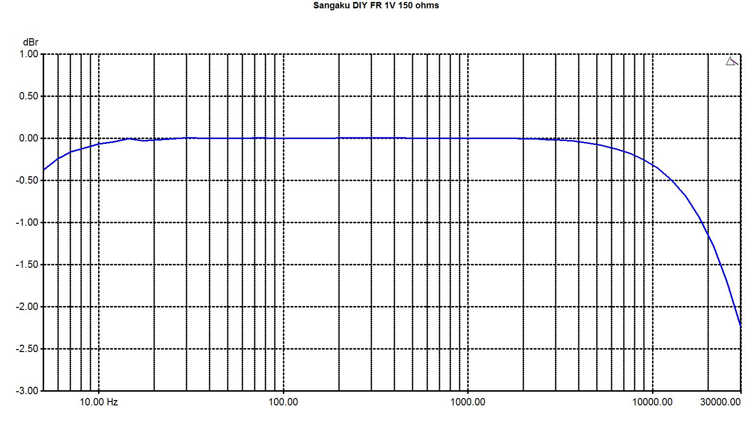
Here is a freq response graph:

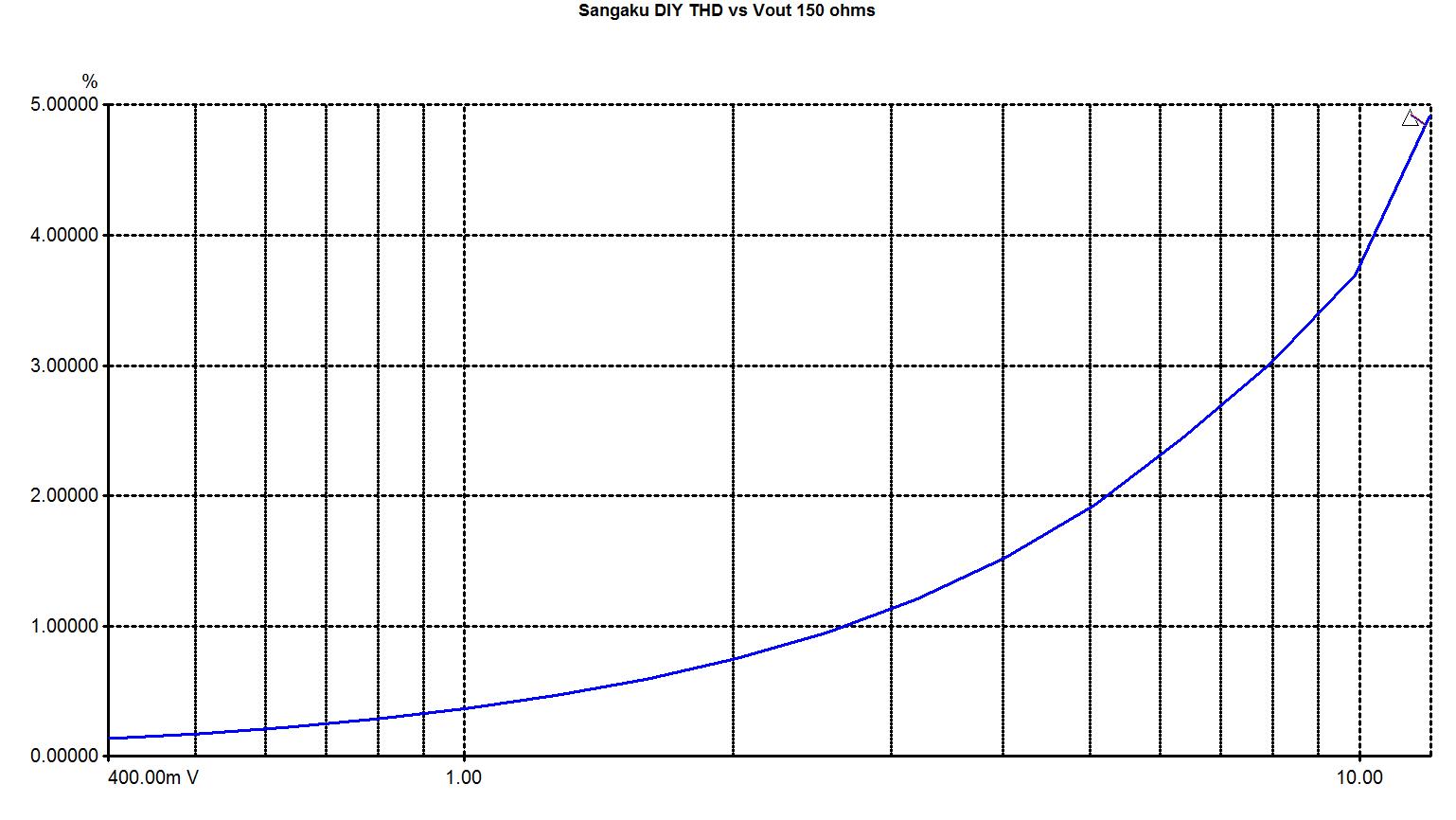
And a graph of THD+N vs. output voltage (in the high gain position - low gain will shifth the whole curve to the left by 12dB):

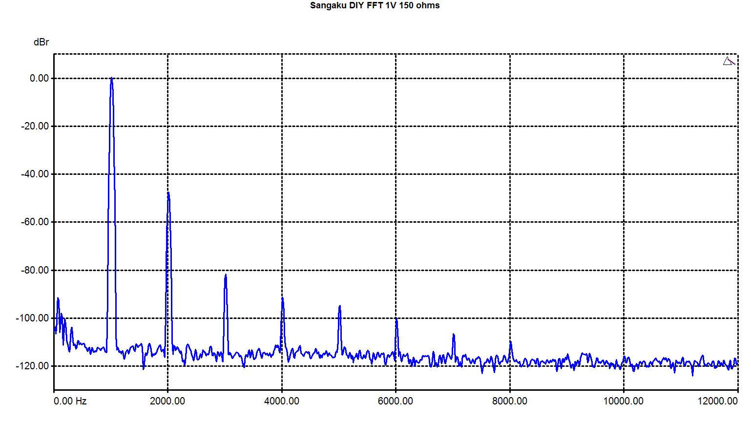
And finally an FFT at 1V:
