Dual opamp experimenter PCB
I was asked about creating a general-purpose PCB to build circuits with opamps. I couldn't find anything like this generally available, so I made one. You can find the PCBs on eBay by clicking here.
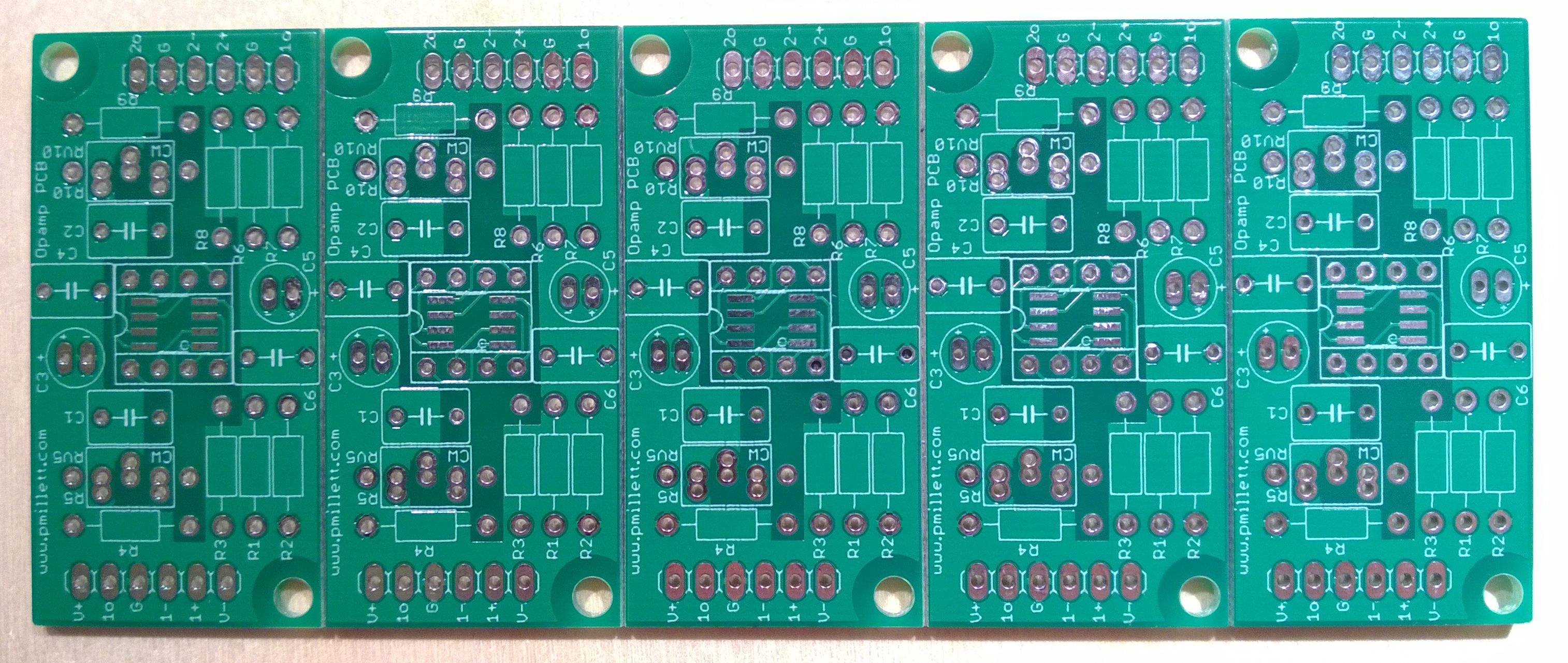
This board supports standard 8-pin dual opamps in either the DIP or SOIC packages. Here's the schematic:
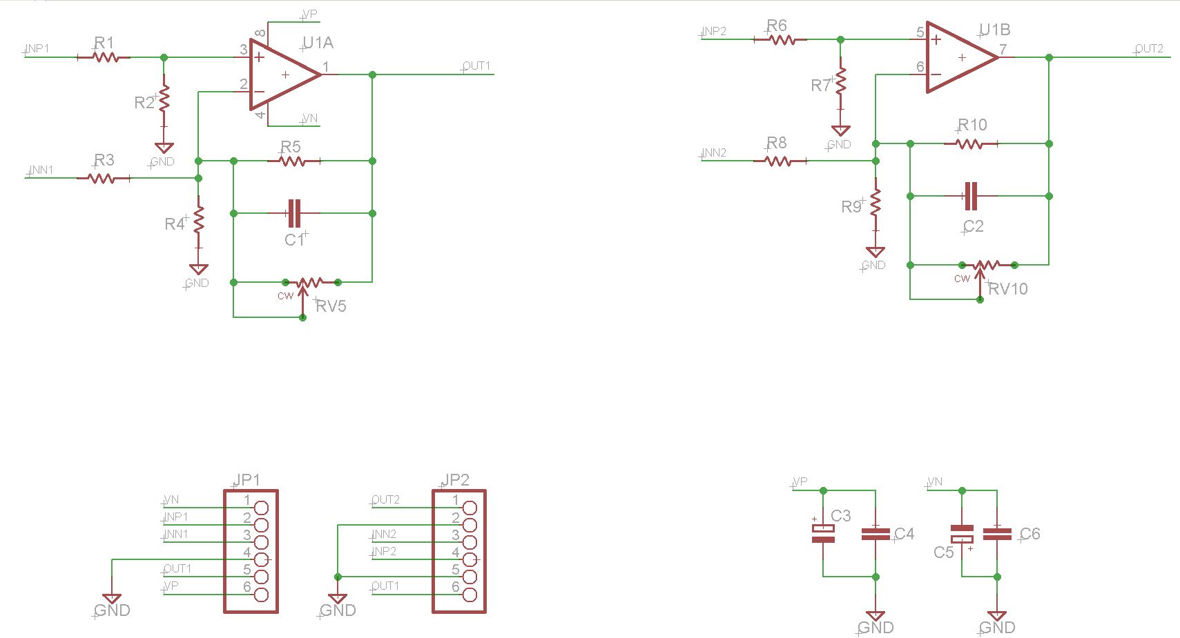
You can see it has locations for resistors to make all the standard opamp circuits - inverting, non-inverting, and differential. Also a spot for a capacitor in the feedback for filtering or integrating. Small (ceramic) and large (electrolytic) bypass capacitor are also provided.
The connections are brought out to two rows of holes on 0.100" centers, on the edges of the PCBs. You can solder wires into these, or mount standard headers to them. they are on 0.100" centers so you can mount the assembly to a prototype board if you want. Two screw holes in the corners let you bolt it down.
The layout has a mostly solid ground plane on the top layer, with copper removed around the inverting input of the opamp.

I had these made in a panel of 5 using a v-score, so they can be broken apart. The panels are available on eBay.