Muting relay PCB
NOTE: The BOM and schematic incorrectly calls out 1N5821 rectifier diodes. These don't mechanically fit on the PCB. use 1N5817 or silimar 1A diodes instead.
With cap-coupled preamps and single-ended power amps in particular, there is often a "thump" heard in the speakers when powering up. I switch the power to my entire system together, and when I added a couple of subwoofers that have solid-state amps (that turn on instantly), that "thump" was pretty annoying.
I've been questioned as to the need of a muting circuit on a tube preamp. The assertion was that the tubes warm up slowly enough that there should be no issue. I beg to differ...
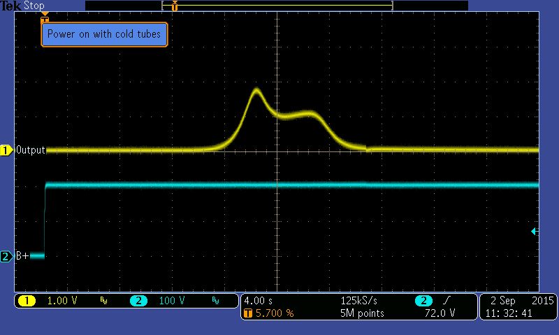
This is a scope shot of the output of "el escorpion" (before the muting circuit) showing power-up with cold tubes. The output goes through a ~1V "bump" as the tubes start conducting. This is a low-frequency thump. If you are using an amplifier and speakers with poor low frequency response, it might not cause you too much of a problem. But even with normal amps you will see the woofer cones do a little dance. And if you have a subwoofer connected, it will sound like somebody just dropped a bag of sand on your roof.
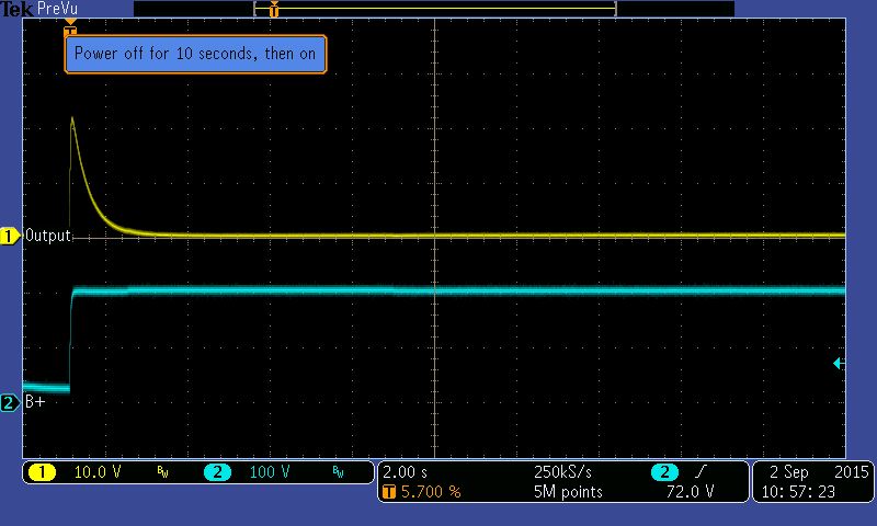
This scope shot hows a bigger danger: what happens if you power off, then back on, if the tubes are still warm. That is a 20V spike on the output. That's enough to pop your woofers. Even if you are careful to never do this, there is always the possibility that the mains voltage may drop out for a short period (it happens all the time here during thunderstorms).
So, when I built "el escorpion", a preamp-in-a-cigar-box, I decided to build a small circuit that could be used to mute the outputs for a period of time while the tubes warmed up.
Here's the schematic (or download it in .PDF format):
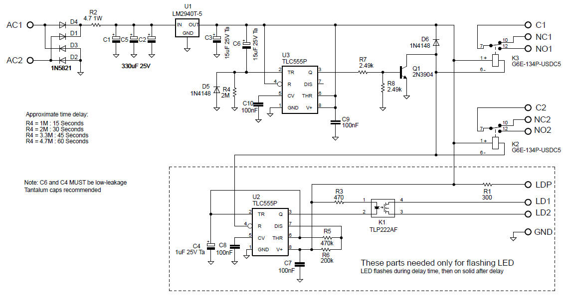
The input can be either AC or DC - typically, the heater supply of 6.3V or 12V is used. In "el escorpion" I was running everything from a 12V DC supply, so I just connected that to the input. If you want, if using DC, you can eliminate the diodes (replacing D4 and D2 with jumper wires)and all but one input capacitor if you want. A 5V LDO regulator is used to generate a 5V supply for the rest of the circuit.
The board has two sections: the upper one on the schematic is used to generate the delay. The lower one is used to make a power LED or pilot lamp flash during the warm-up time. If you don't want this feature you can leave out all the parts inside the dotted box on the schematic. I like the feature, sine it lets you see that the power is on but output is muted. After the mute period expires, the LED is lit solid.
The delay and flashing is implemented using 555 timer ICs (TLC555 form TI). The delay time as shown is about 30 seconds. You can make C6 or R4 bigger to increase the time, or smaller to decrease it.
I used two SPDT relays, so I could get a contact rating high enough for a power amp. These relays are rated for 3A, which is OK for power amps up to 50 watts or so. If you need something bigger, you can use the output to switch the coil of a bigger relay. Note that the contacts are rated for up to 250VAC only, and not rated for high voltage DC - do not use this to directly switch a high-voltage B+ supply!
The LED or pilot light output is switched by a small MOSFET solid-state relay. This can switch AC or DC at low current. If you use an LED, you can connect the anode to the LDP terminal and cathode to LD1, and jumper LD2 to GND. This will use the regulated 5V and resistor R1 to drive the LED. If you are using some other form of light (an external lamp or LED with resistor), just use the LD1 and LD2 terminals as a switch and wire it in series with the lamp.
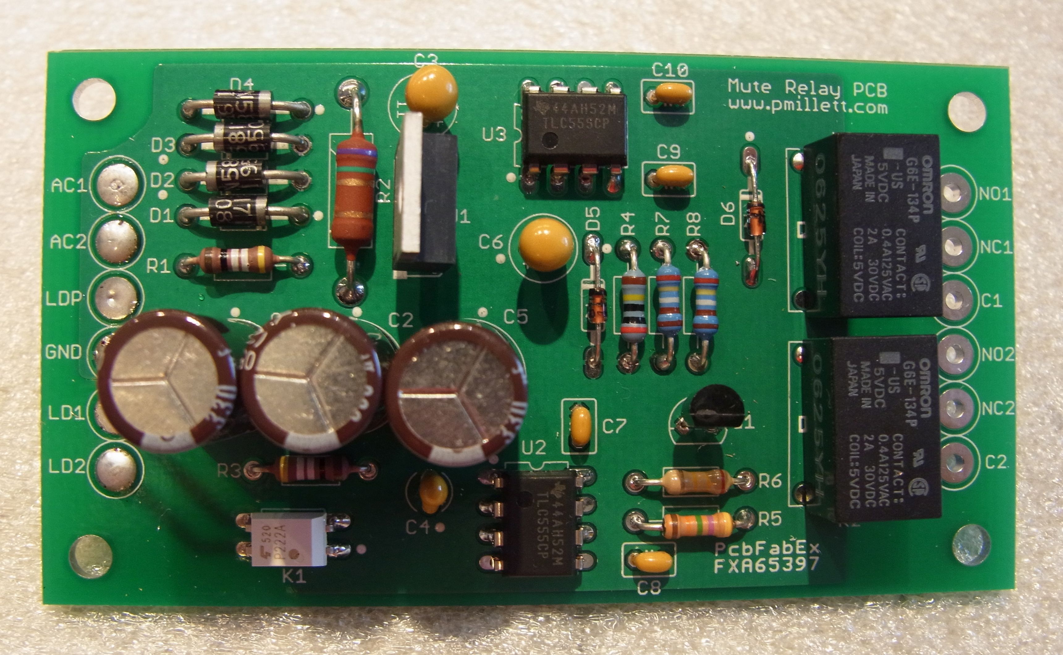
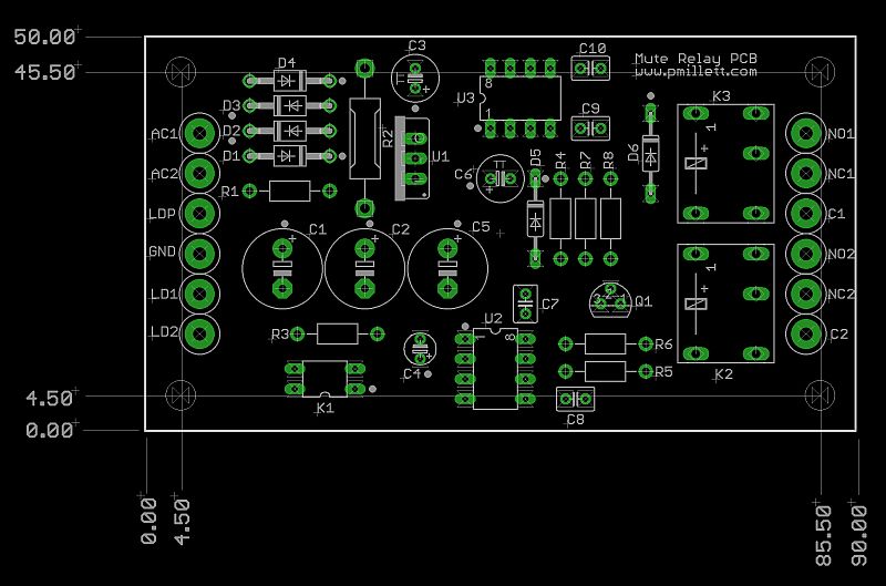
The circuit is simple enough that you can build it on perfboard. Since I like designing PCBs, of course, I made a PCB for this. The PCB is 50mm x 90mm:

The parts can all be purchased from Digi-Key. Here is a parts list (Bill of Materials) in .XLS or .PDF form.
Also, an updated BOM with Mouser part numbers.
I will sell the PCBs in my eBay store.