Hybrid amp with adjustable damping
PLEASE READ - Commercial usage of information on this site:
I consider all the information that I post here to be in the public domain. So, you can use it however you want, for commercial or non-commercial use.
That said, I would appreciate it if you at least let me know if you are going to use any of the circuits or especially PCB Gerber files to make commercial products, or to sell bare PCB's.
There are some cases where products are being sold not only with my permission, but active involvement. The "Millett Hybrid" effort and others at HeadFi are examples (and excellent models of how the DIY community should work, in my opinion). There are other cases where I have asked vendors to sell PCB's as a service to hobbyists. And there are other cases where companies are manufacturing and selling PCB's, chassis, etc. without contacting me at all.
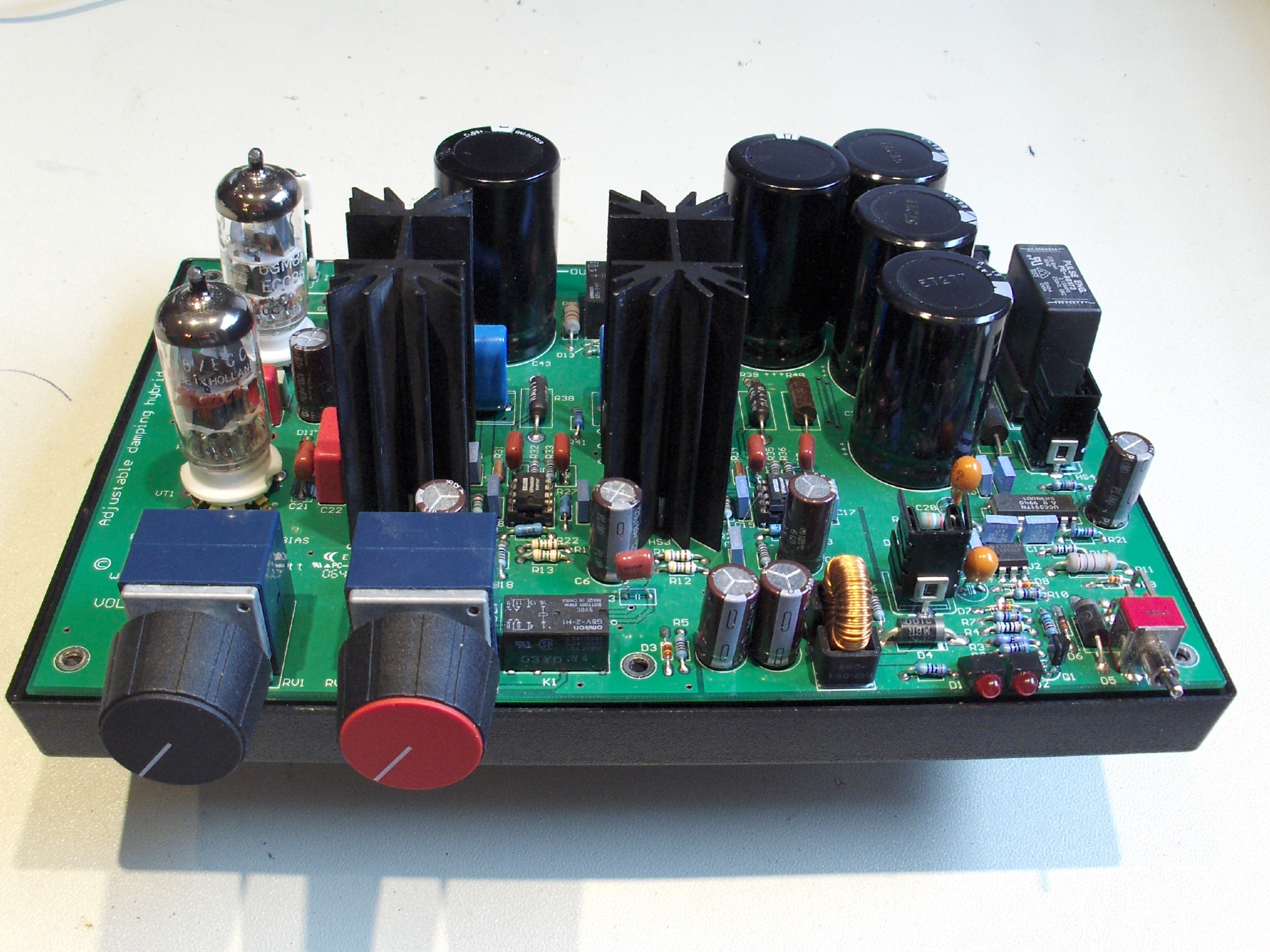
I've had this little guy running for quite some time:
It's a hybrid amplifier that uses low-voltage tubes and a power opamp output stage. It runs from a 24V to 48V, 100W desktop power supply. And the unique thing (if that wasn't unique?) is that it has a "damping" control that lets you set the output impedance from near zero up to about 100 ohms.
Yes, there is a long story associated with this.
I started out wanting to design a simple hybrid amp to drive speakers that, like the hybrid headphone amp, could be built without having to touch any hazardous voltage. That precludes "normal" tube circuits, and also line voltage (power supplies). The power supply is the hard part... the lack of any readily available bipolar (+/- voltage) supplies big enough to drive a speaker meant that the amp has to run on a single power supply. So, this amp runs on a single supply, and has (gasp!) output coupling capacitors.
To get the ~100 watts needed, the only reasonable choice was a desktop switching power supply. The problem with that is that I really didn't want to rely on the supply to provide the big AC current needed to drive a speaker. No problem, you say, just add a bunch of capacitance. This I did, 30,000uF to be precise. But a switcher doesn't like to start up into a huge output capacitor. Most of them just sit there and cycle on and off. So, I had to add a "soft-start" circuit to limit the amount of current that flows in to charge the caps. Think of it as a precise inrush limiter. It also serves to limit power in the event of a short circuit. All a bit of complexity, but in the interest of safety...
Now, a single-ended cap-coupled amp will make a horrendous "thump" when you turn it on and off. So, I had to add a time-delay circuit and relay to disable the outputs at power-up and power-down. A little more complex...
About the same time I was developing this idea I was also playing around with pentode amps and high output impedance amps to drive full-range speakers. I found that many full-rangers really prefer a high Zo, maybe even a current source. Since simplicity had been lost in this project anyway, I added a current feedback loop to the output stage, and adjustment that lets you vary between current feedback and voltage feedback. The result is that you can vary the effective output impedance from about 1/2 ohm up to 100 ohms. Cool!
It's very interesting to be able to tweak the Zo as you listen to music. Definitely on my Fostex's, better sound is achieved at a highish Zo (maybe 16 ohms). Other speakers sound really bad at high Zo. They're all different...
I took this amp to the European Triode Festival in 2006 to demonstrate. The effects are not subtle... in fact I think I got a new, well deserved nickname: "Mr. Subtle". There was no consensus about what sounded best, either - some preferred an all-out current source, others a voltage source.
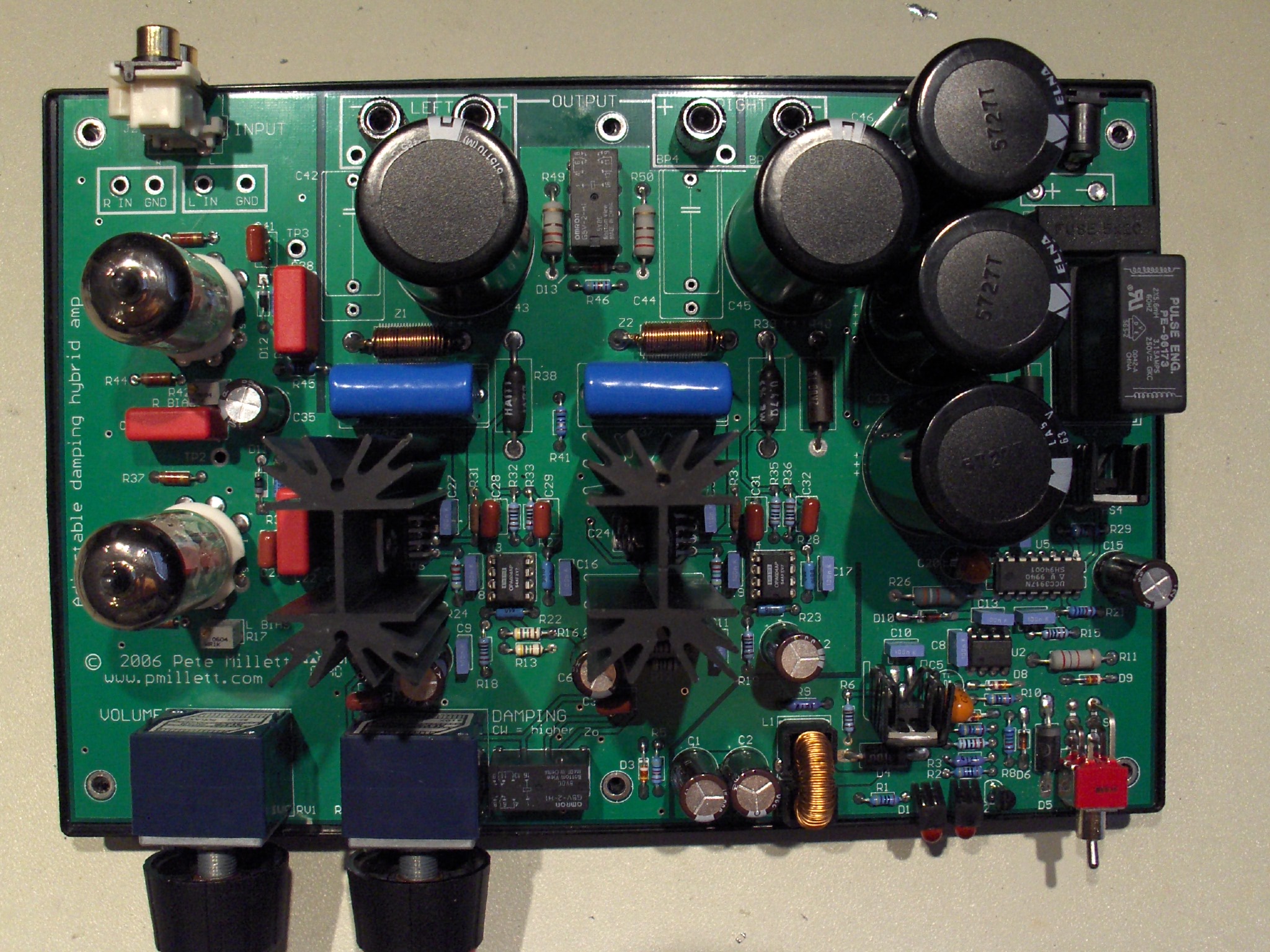
OK, enough of the narrative, here are the details:
The amp uses ECC86/6GM8 tubes, with a CCS diode load, driving a TI power opamp output stage. A current sense resistor is used in series with the output. The voltage across the resistor is amplified by an opamp, and this current feedback as well as the amp output is applied as feedback to the power opamp through a pot.
Running on a 48V supply, the amp puts out about 13V RMS - a bit over 20 watts per channel into 8 ohms. It's distortion is typically tubey, about 0.7% THD at 1W out, virtually all second harmonic. So it does sound like a tube amp.
For those of you that claim an amp could not possibly be any good if it couples the output through (big honkin' electrolytic) capacitors, let me remind you of AC circuit theory: the signal you hear is virtually always going through big honkin' electrolytic caps. They're in the power supply. Where do you think the signal power comes from?
Here are the details:
Schematic (396k PDF file)
Eagle CAD files (96k ZIP archive)
Gerber files (487k ZIP archive)
Bill of Materials (BOM) (20k XLS file) (50k PDF file)
Oh well, so much for simple. I never did put this all together for a magazine article as was my initial intention. So here it is. It's been running my computer speakers...