Tube power supply PCB with bias supply
For my 815 amp, as well as other projects, I designed a PCB that provides HV rectifiers and filter caps plus an isolated supply that can be used as a negative bias supply.
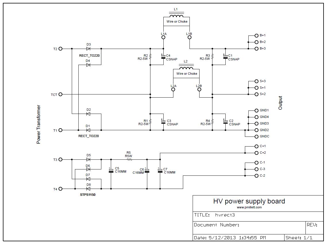
It's pretty self-explanatory. The HV side uses a bridge made of TO-220 rectifiers (I would suggest a SiC Schottky) with a center tap. This provides two voltages, a high voltage, and a lower (roughly 1/2 the high voltage). The filter caps are arranged in series. This allows you to generate a high B+ (for example, 600V) and a lower voltage for drivers and screen supplies.
Pads are provided for chokes in both the B+ and S+ (lower voltage) path. If you don't need a choke you can install a jumper wire.
The bias supply is a separate bridge rectifier and CRC filter. There's pads on the PCB to allow you to connect the positive side (C+) to GND, so you get a negative bias supply (C-). You do not have to make this connection, so you could also use it to generate a separate, floating power supply voltage.
For help designing a power supply, I highly recommend Duncanamps PSUD simulation program. It will help you figure out optimal values for the caps, chokes, and resistors.
Here's the schematic (or download a PDF file):
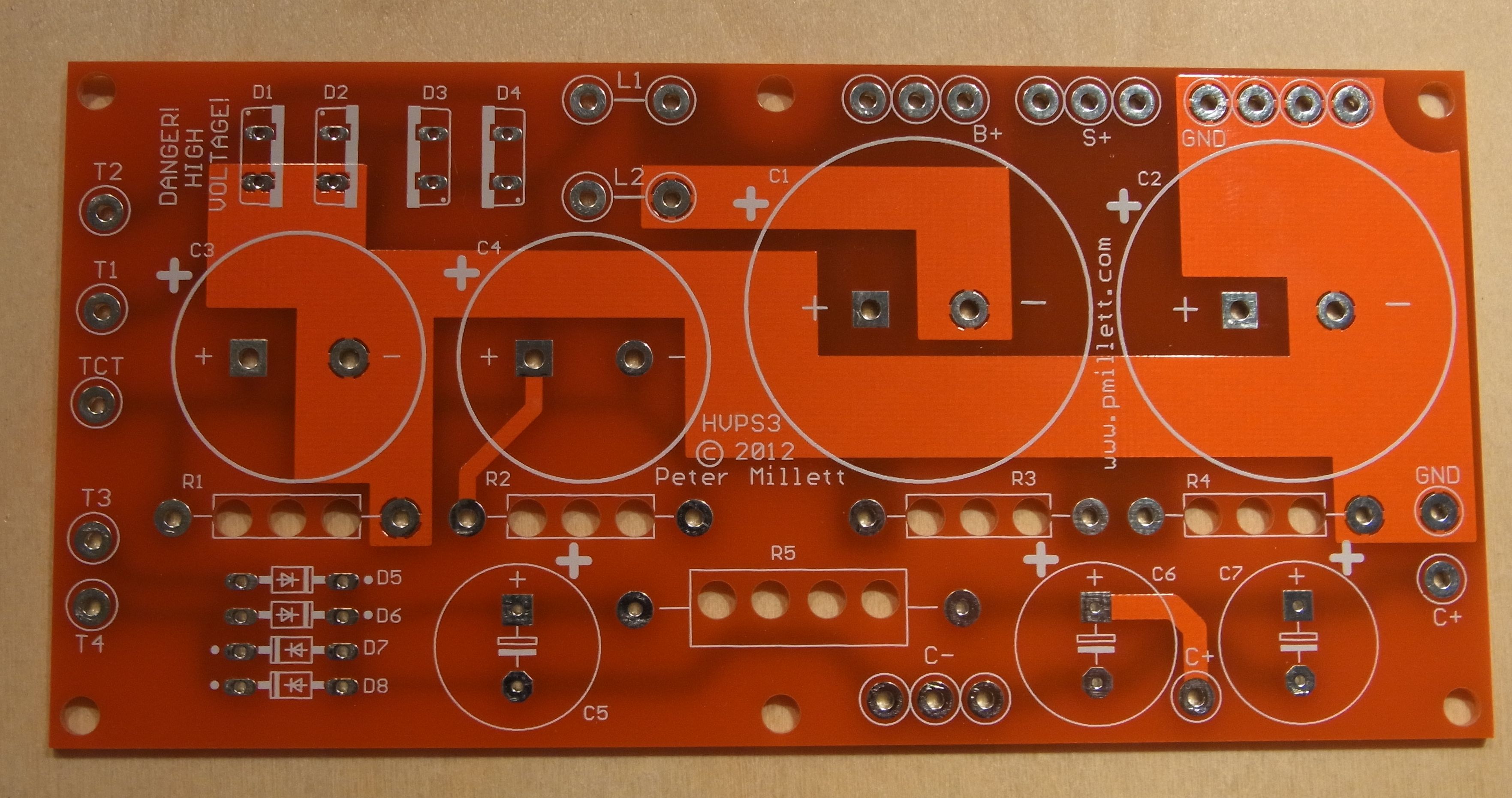
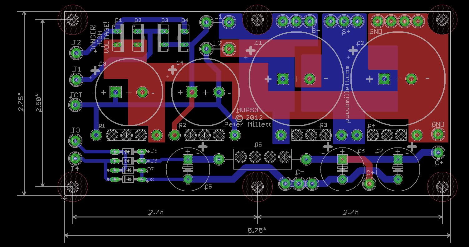
Here is the PCB, available on eBay:
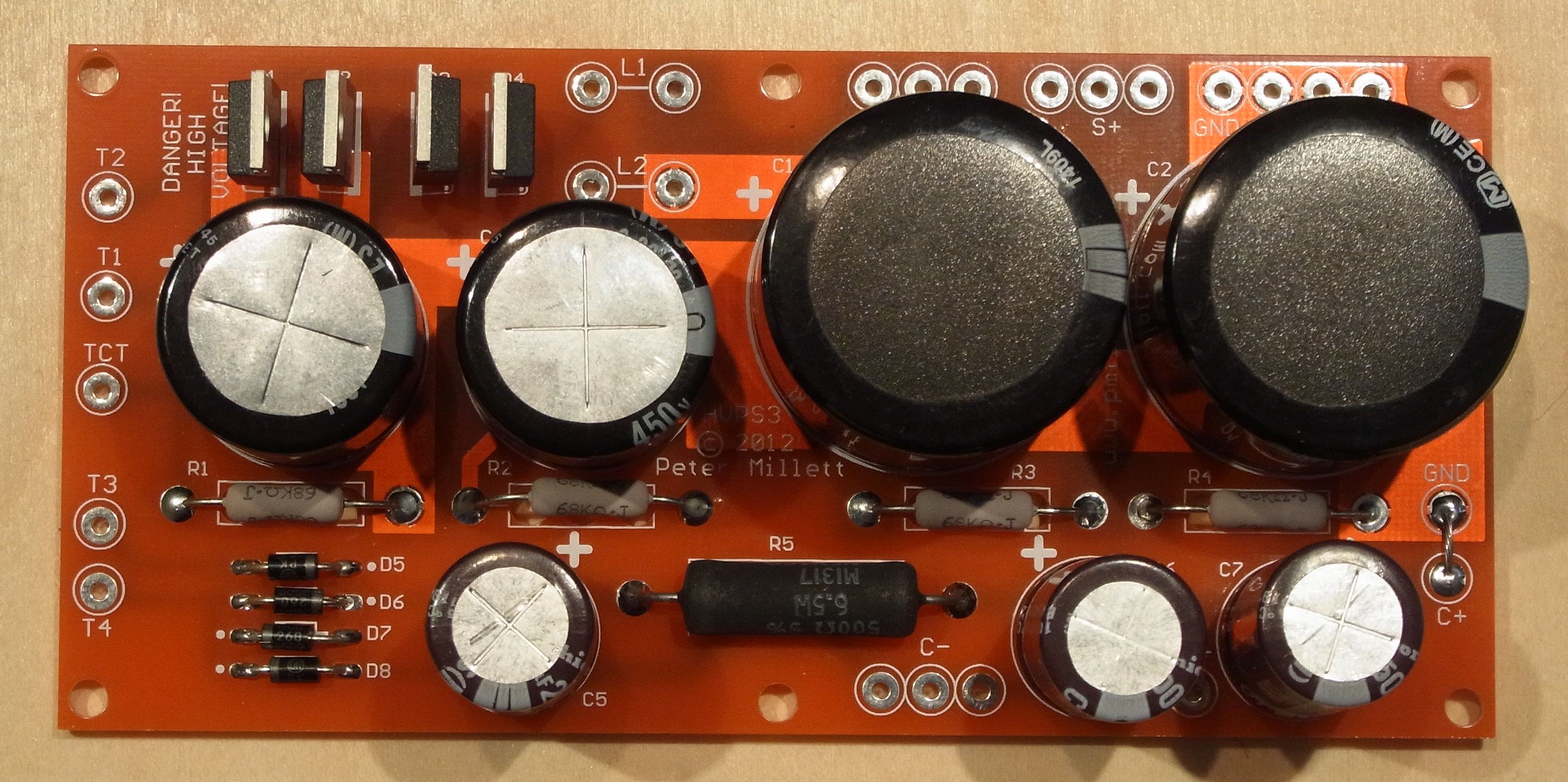
The assembled PCB: