The Glowing Hybrid Amplifier
This odd little amp was something I designed and built for a shootout at the European Triode Festival in 2007. The topic was "White Light" - amplifiers that use thoriated tungsten tubes. Some great photos of the event can be found here and here.
Since it's impractical to tote an enormous tube amp from the US to Europe, I decided on an approach that uses a solid-state power output stage and a small thoriated tube as a voltage amp. I tried out just about all the small tubes of this type that I could find, and wound up using the 703A.
The 703A is a small UFO-shaped triode designed for radar jammer service. I found that it made a pretty decent low-level amp when run with a B+ of 48V and a ~1mA CCS plate load (!), so that's what you find in this circuit. It is coupled to TI (Burr-Brown) OPA548 power op-amps, which drive the speakers. Power is +/-24V, generated from some Vicor DC/DC converter modules. The 1.15V filament is supplied by another pair of isolated DC/DC converters, running form the +/-24V (48V) DC supply, with significant common mode filtering.
I set the amplifier up to sound somewhat like a single-ended 300B amp. It puts out about 20 watts into 8 ohms, and has an artificially high (for a solid-state output stage) output source impedance of 1 ohm, to emulate a tube amp output. It has about 0.3% - 0.5% THD at 1 watt output, dominated by 2nd harmonic, as a single-ended tube amp should be.
Here are some plots:
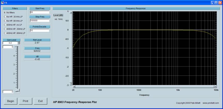
Frequency response... just about perfect.
THD+N vs. Frequency... pretty flat, no slew rate issues here.

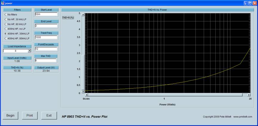
THD+N vs. output power... it hits 5% just over 20 watts.
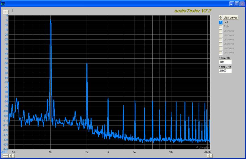
And finally an FFT of the output. Dominated by 2nd harmonic, like a SE tube amp... but there are crossover distortion products from the solid-state output stage that extend all the way to 20kHz, albeit 90dB down. Note the measurement floor is -135dB!
Here's the basic amp circuit:
The 703A filaments are supplied from a DC/DC converter with some filtering:

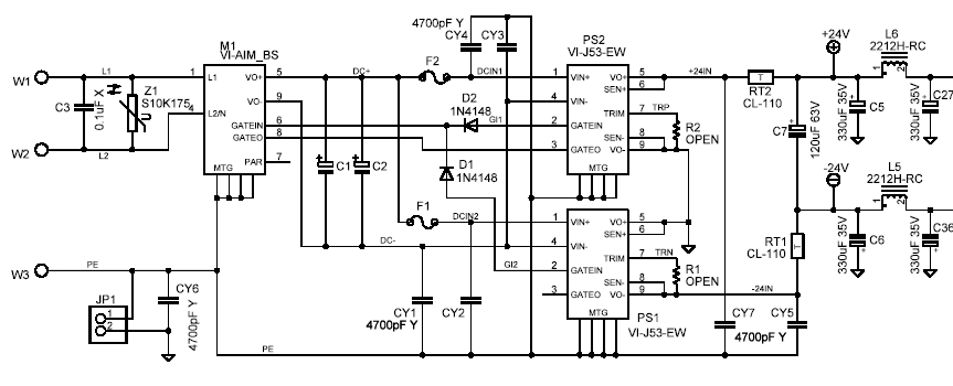
The power supply uses Vicor modules: An IAM AC input module (filter and rectifier with some supervisory functions) and two JI-J53-EW modules, which turns rectified 120VAC into 24V. One is connected for +24 and the other -24.
Also, a delay circuit mutes the output until the thing has warmed up:
For full details, download the full schematic (PDF file).
I also have detailed AutoCAD drawings, Eagle CAD source, and PCB files for this project. If you are interested email me.
The mechanical design and fabrication of this took me a very long time... it's pretty complicated. The chassis is made from a maple "U"-shape (with box joints, no less!), and aluminum extrusions and sheets. There are two heatsinks, one for the power output stage and one for the power supplies. Here's what it looks like in AutoCAD:
Below are a number of detailed photos showing the construction. The photos are 640x480 and are hyperlinked to original full-size pictures if you click on them..
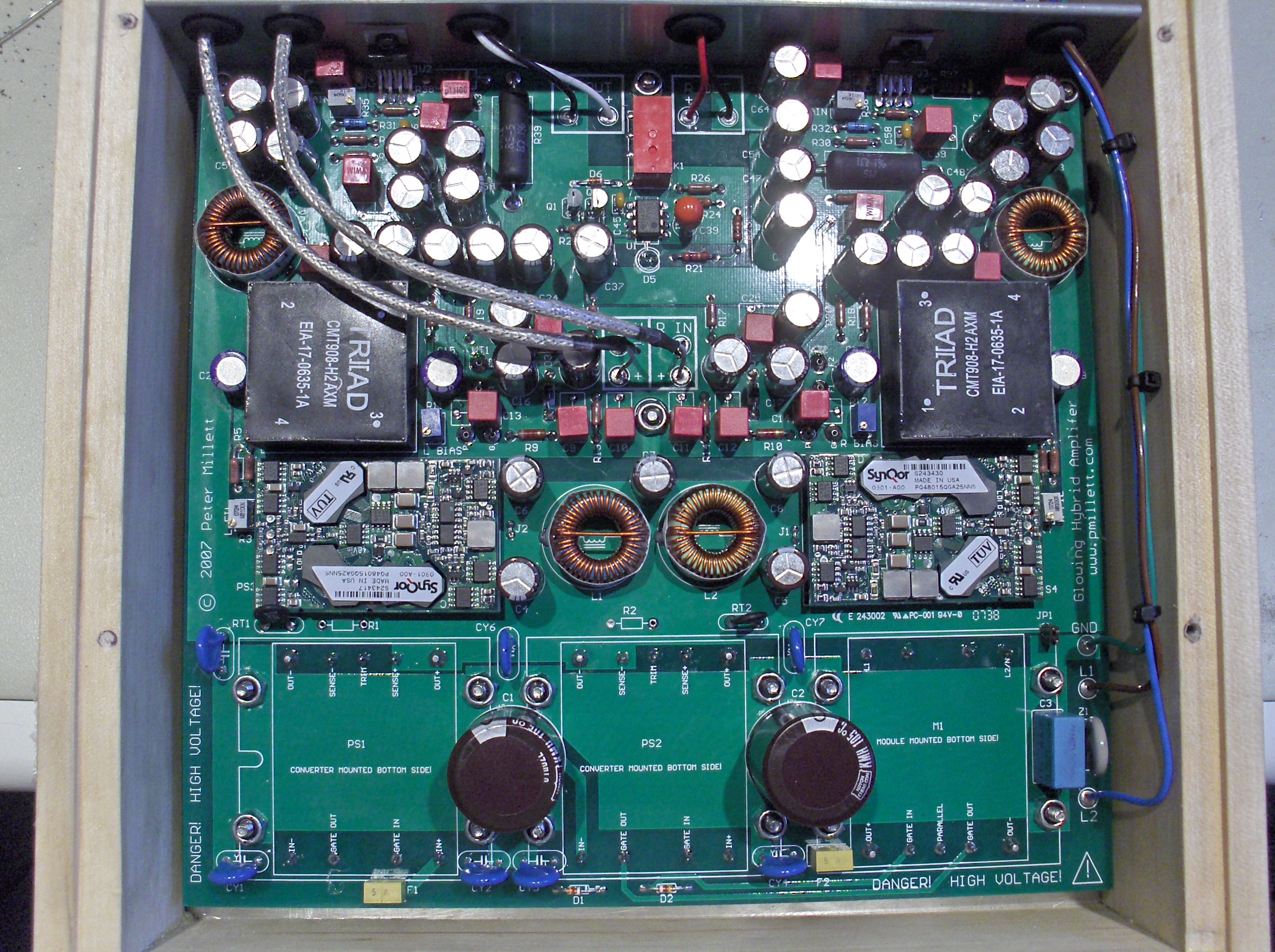
Inside view... power opamps are at the top edge of the PCB connected to a big metal T-extrusion that is connected to one of the two heatsinks. The Vicor converters are at the bottom edge mounted on the opposite side of the PCB, so they can attach to the second heatsink. Filament converters and common mode chokes (big black square things) are seen in the center.
An angled inside shot. Here you can see the power opamps, and the wiring that passes through the T-extrusion to the back panel.

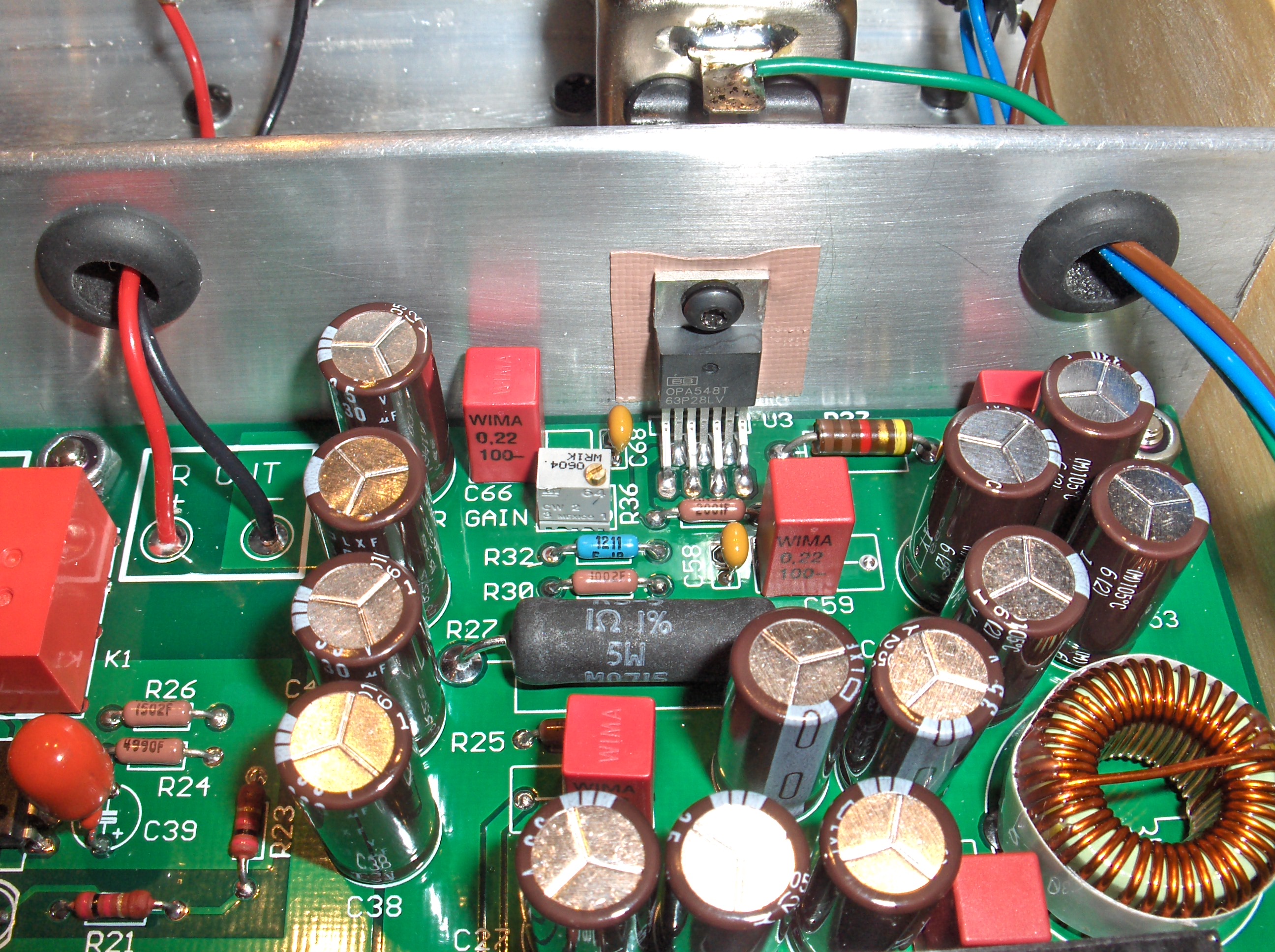
A detailed shot of an OPA548's mounted to the T extrusion.
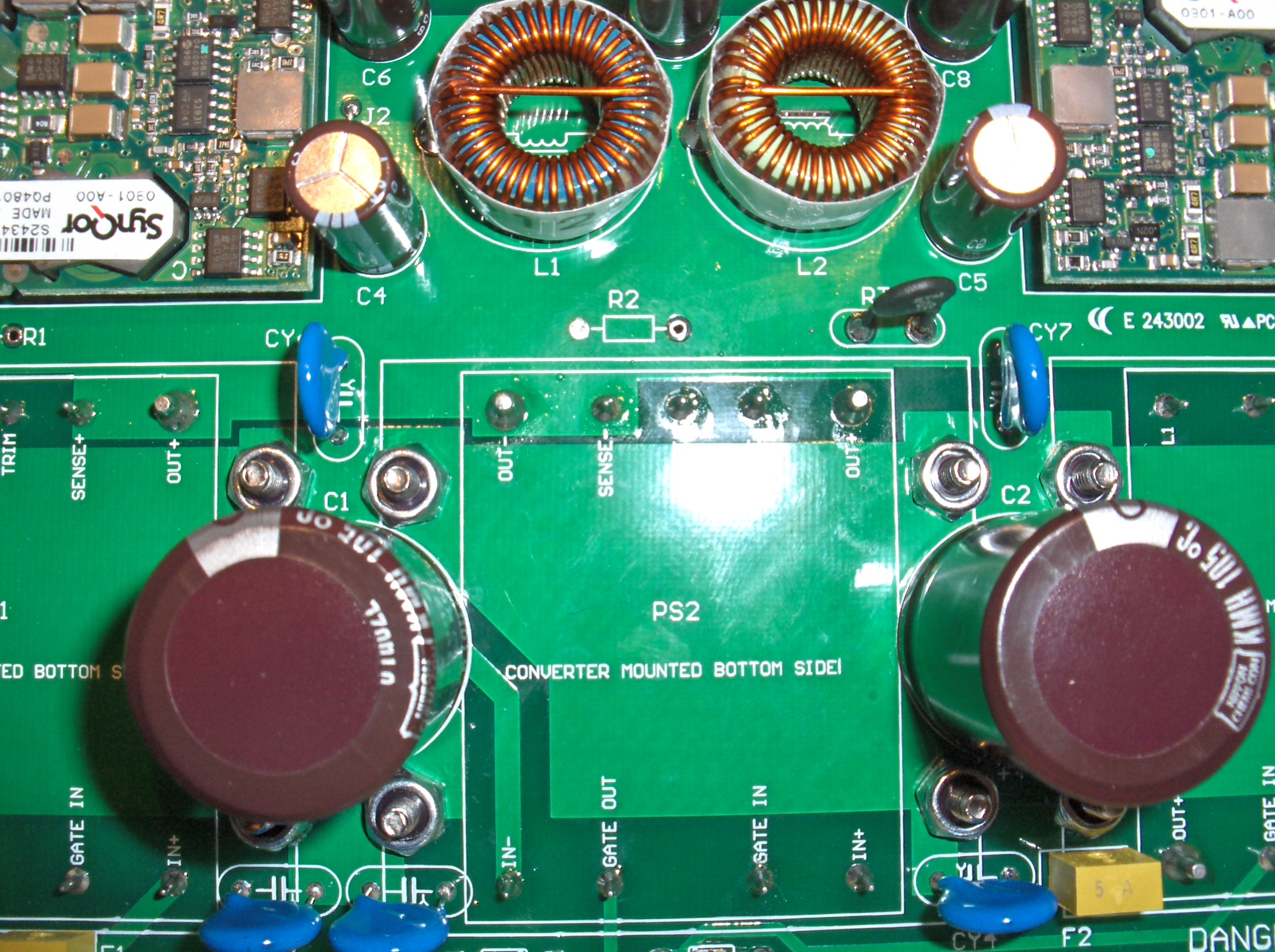
A detailed shot showing the power supply are of the PCB
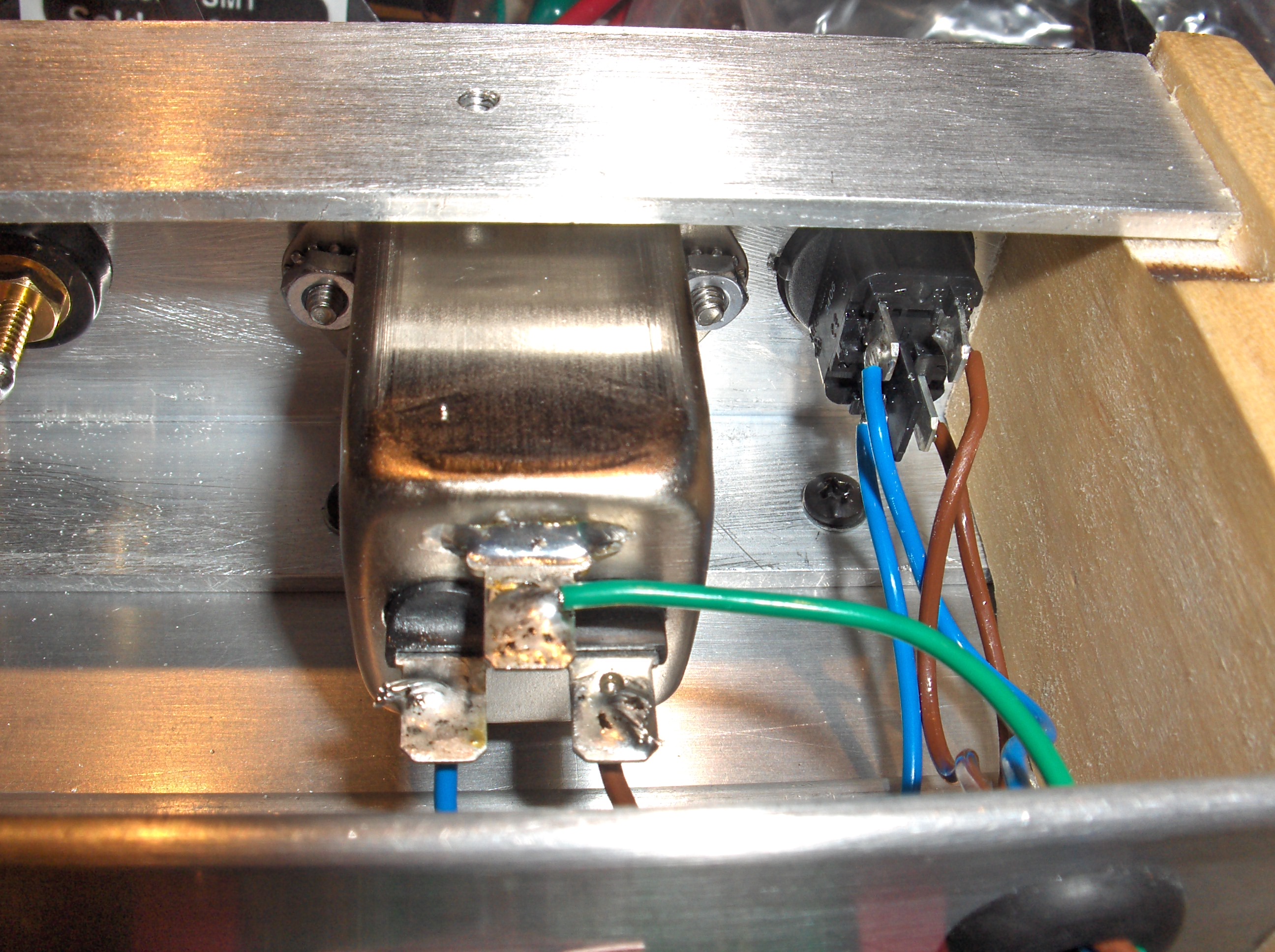
A detailed shot of the input wiring on the back panel...
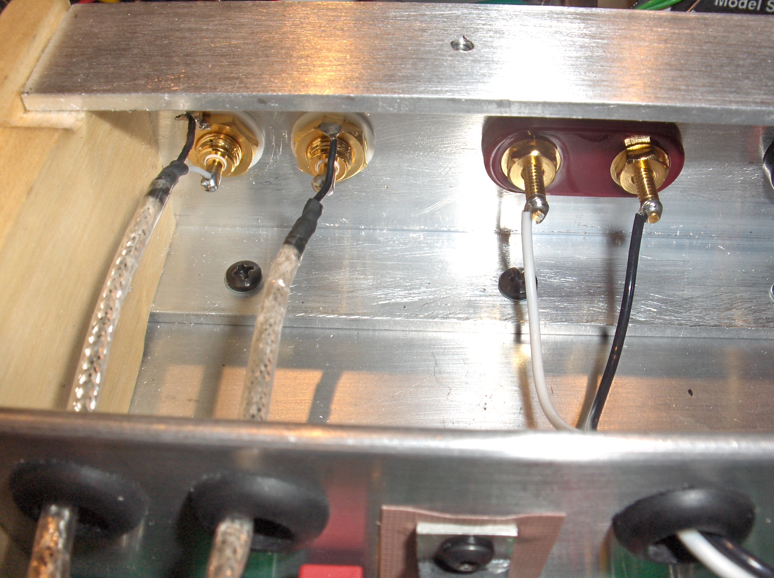
...one of the speaker wiring...

...and one of the AC wiring
Here is a view of the top side of the PCB. You can see the Vicor modules and the "home made" tube sockets. The white LED you see is a bi-color LED that starts out red, then after the speaker muting delay times out, changes to green.
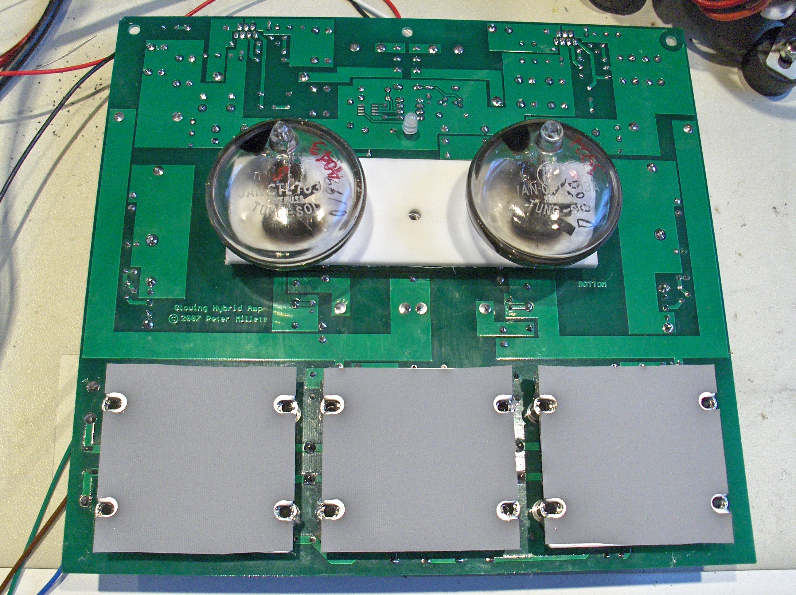
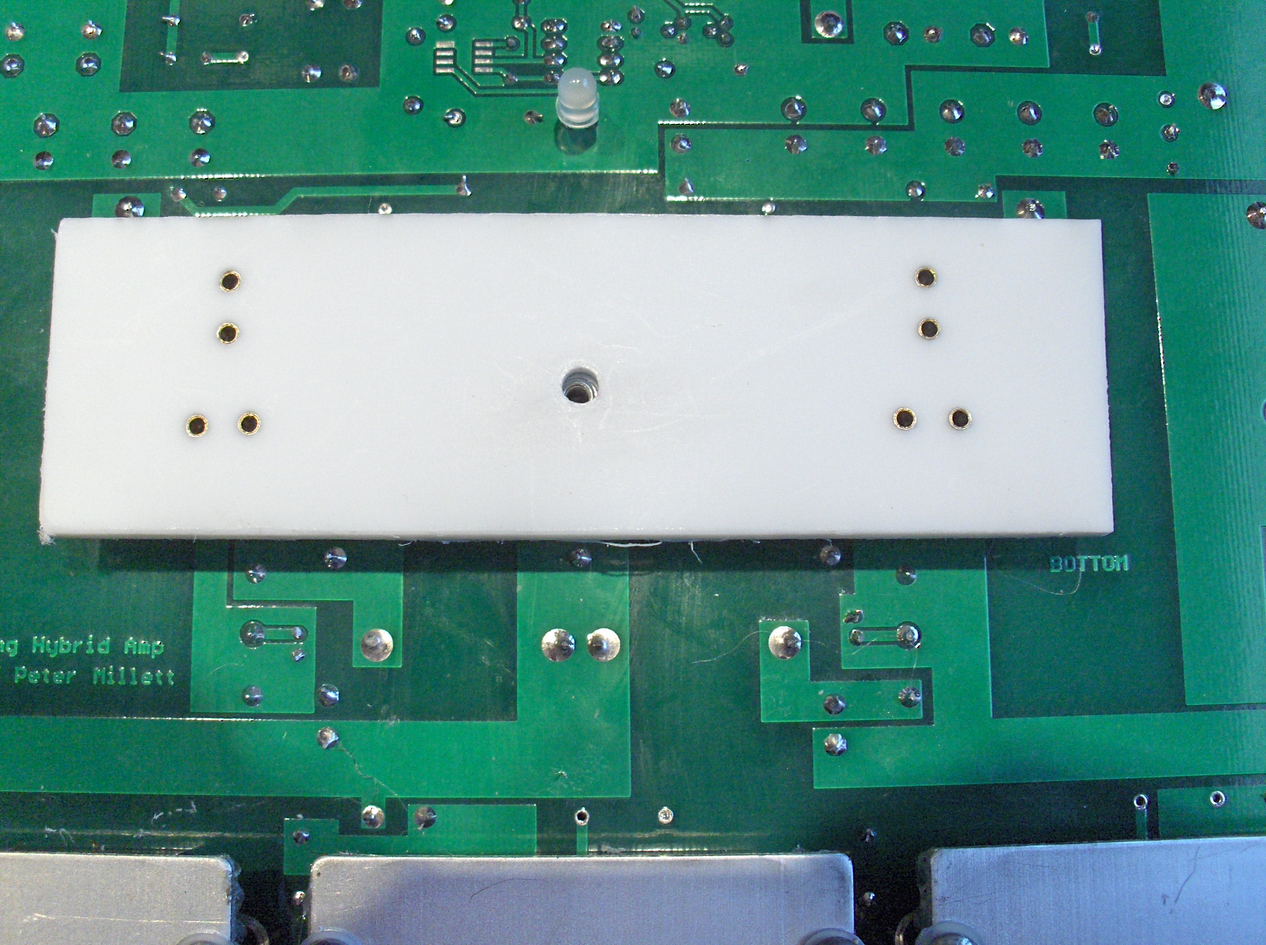
The next two photos show how the sockets work. First, PCB socket pins are soldered into the board. Small Teflon spacers and silicone o-rings are added to the outermost pins to act as spacers/supports.

A solid Teflon sheet is then added over the top. Large round cutouts in the chassis will allow the tubes to plug in.