Experiments with an Ixys current regulator as a CCS plate load
One day, while researching possible motor driver IC's for my "day job", I ran across a device that I thought might be useful for my vacuum tube obsession, uh, hobby. It is a high-voltage current regulator IC from Ixys.
Ixys had several different flavors of this part, which is designed to regulate between 1mA and 100mA, with a maximum voltage of 350-450V. A quick look at Digi-Key's inventory found some IXP10M45S parts, which is an adjustable version of the part (2-100mA) that is rated for 450V. This is a three-terminal device; current adjustment is made by varying a resistor connected between the "gate" and "cathode" of the part, while the "anode" is connected to the positive power supply and the "cathode" to the tube plate.
I'm not sure what's really inside this part. Although with three terminals the part acts a lot like a very high transconductance, depletion-mode FET, I suspect that there is actually an error amplifier in it driving a standard MOSFET (and if you look at the "fixed" regulators in the family, they are shown that way).
Here's the datasheet for the IXP10M45S part. Unfortunately it doesn't give a lot of detail, nor any dynamic performance specs. Note that there is a typo on this data sheet - the dynamic resistance at 10mA (resistor of 300 ohms) is incorrectly listed as 10K ohms; it actually is 100K.
This sounded like a good plate load to me! So I bought a handful and did some experiments....
Low-power test
For the first test, I tried the IXP10M45S in a 6SN7 driver circuit. I connected both halves of the 6SN7; one as a normal grounded-cathode amp with a plate load resistor running about 5mA, and the other with the IXCP10M45 as the plate load, set at 5mA. The grids were both driven from my HP audio analyzer, and the outputs loaded with 250k (in parallel with the analyzer's input, which is 100k).
I made no effort to optimize the operating point of the resistive-loaded stage for any particular use, and you can certainly move the op point around and get more (or less) gain, maximum output, and distortion. I just picked this one for comparison.
Here is the schematic of the test circuit:
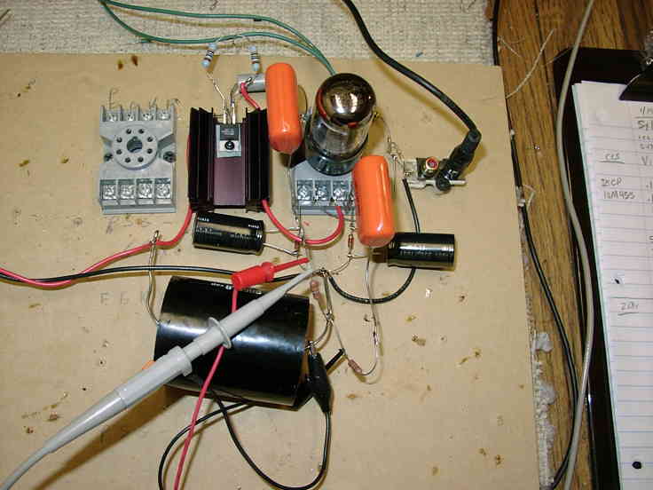
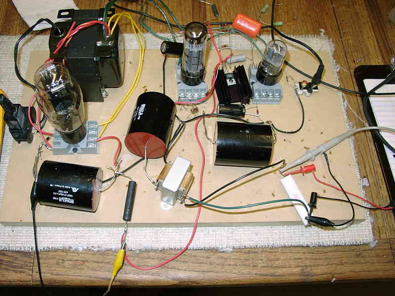
And a photo of the breadboarded setup:
I measured distortion, gain, and frequency response for the two circuits to see if the current source added any distortion products, or adversely affected the response in any way. Here's the results:
Resistor-loaded circuit:
|
Vin RMS |
Vout RMS |
Vout relative |
Gain V/V |
Freq. HZ |
THD percent |
Notes |
|
0.1 |
1.31 |
0 dB |
13.1 |
1000 |
0.16% |
All 2nd harmonic plus noise |
|
0.1 |
1.27 |
-0.3 dB |
12.7 |
20000 |
0.17% |
All 2nd harmonic plus noise |
|
1.0 |
13.1 |
0 dB |
13.1 |
1000 |
1.32% |
All 2nd harmonic |
|
1.0 |
12.7 |
-0.3 dB |
12.7 |
20000 |
1.43% |
All 2nd harmonic |
|
1.0 |
9.29 |
-3.0 dB |
9.29 |
79000 |
2.2% |
Mostly 2nd harmonic (-3dB frequency) |
|
3 |
38.7 |
0 dB |
12.9 |
1000 |
4.5% |
Mostly 2nd harmonic |
|
3 |
37.3 |
-0.3 dB |
12.4 |
20000 |
5% |
Mostly 2nd harmonic |
|
3.2 |
41.2 |
-- |
-- |
1000 |
5% |
Mostly 2nd harmonic (5% THD level @ 1 kHz) |
|
3.0 |
37.3 |
-- |
-- |
20000 |
5% |
Mostly 2nd harmonic (5% THD level @ 20 kHz) |
CCS-loaded circuit:
|
Vin RMS |
Vout RMS |
Vout relative |
Gain V/V |
Freq. HZ |
THD percent |
Notes |
|
0.1 |
1.87 |
0 dB |
18.7 |
1000 |
0.08% |
All 2nd harmonic plus noise |
|
0.1 |
1.73 |
-0.63 dB |
17.3 |
20000 |
0.13% |
All 2nd harmonic plus noise |
|
1.0 |
18.7 |
0 dB |
18.7 |
1000 |
0.75% |
All 2nd harmonic |
|
1.0 |
17.5 |
-0.57 dB |
17.5 |
20000 |
1.2% |
All 2nd harmonic |
|
1.0 |
13.1 |
-3.0 dB |
13.1 |
53000 |
2.6% |
Mostly 2nd harmonic (-3dB frequency) |
|
3 |
56.0 |
0 dB |
18.6 |
1000 |
2.2% |
Mostly 2nd harmonic |
|
3 |
51.6 |
-0.3 Db |
17.2 |
20000 |
3.8% |
Mostly 2nd harmonic |
|
5.9 |
101.8 |
-- |
-- |
1000 |
5% |
Hard clip 2nd + 3rd (5% THD level @ 1 kHz) |
|
3.8 |
64.7 |
-- |
-- |
20000 |
5% |
All 2nd harmonic (5% THD level @ 20 kHz) |
I tested a number of 6SN7's of different manufacturers, just to make sure that the differences between tube sections weren't influencing my measurements. They all looked about the same. The numbers above were generated with a Sylvania 6SN7WGTA, with well-matched triode sections.
From these tests, it looks to me like the Ixys part performed well. Compared to the resistive-loaded stage, both at low and high output levels it lowered the distortion quite a lot, and didn't introduce any odd-order harmonics anywhere that I could see. The gain was also considerably higher, obviously, because of the high impedance that the current source presents. Probably the only downside to using this type of part (not specific to the Ixys part, but any SS current source) is that clipping can be more abrupt than with an all-tube system. But right up to clipping, the distortion was all typical SE tube, 2nd harmonic distortion.
Higher-power test
The next test was to see how this part might work as a plate load for a parallel-feed SE amp output stage. I didn't have a 2A3 available, so I did a circuit using a triode-connected EL34. The circuit looked like this:
The EL34 is biased at 65mA and 300V, with a grid voltage of about -25V, by the IXCP10M45S and the 383 ohm cathode resistor. At this op point both the EL34 and the IXCP10M45S are dissipating about 20W.
At first, I tried the circuit into a 3K resistive load. At 5% THD, the output voltage was 69V RMS @ 1 kHz. The distortion was entirely 2nd harmonic. I could raise the output to 110V RMS before clipping, at 8% THD, again all 2nd harmonic. The frequency response was only down 1dB at the 100kHz limit of my analyzer. Obviously, no problem with high frequency! THD was constant over frequency, up to the point where the measurements start to get inaccurate because of bandwidth limitations in the analyzer (over 50kHz or so).
I next coupled the output through the el-cheapo 70V Radio Shack line output transformer. It was set up to reflect an impedance of about 2000 ohms to the EL34, driving the 2.5 watt tap on the primary, and using the 8 ohm tap on the secondary with an 88 ohm resistive load. With this, I got about 4.8V RMS into 8 ohms, or 2.65 Watts, at 5% THD. That's about all this little transformer can handle. I think with a decent transformer you could get a bit more from it.
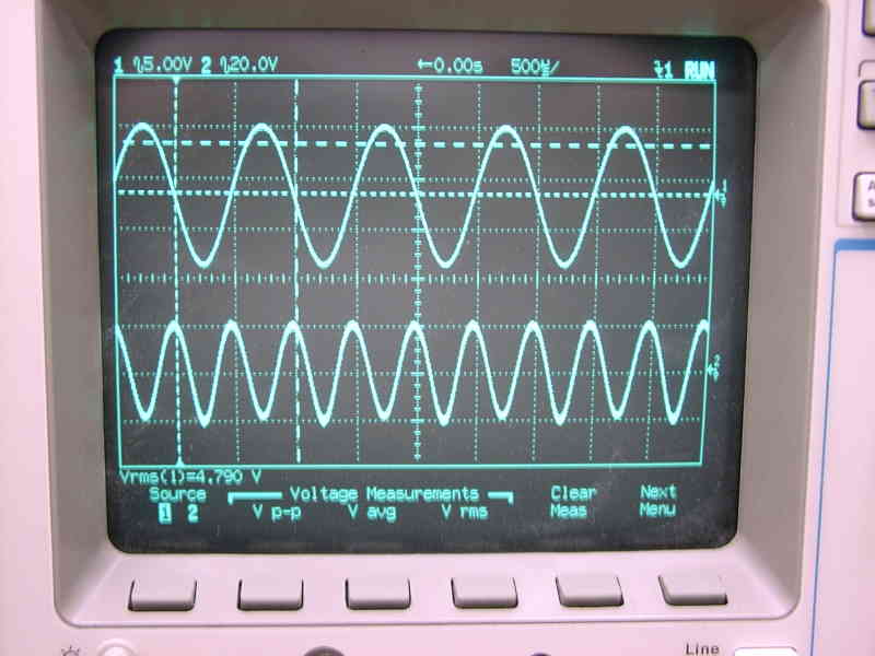
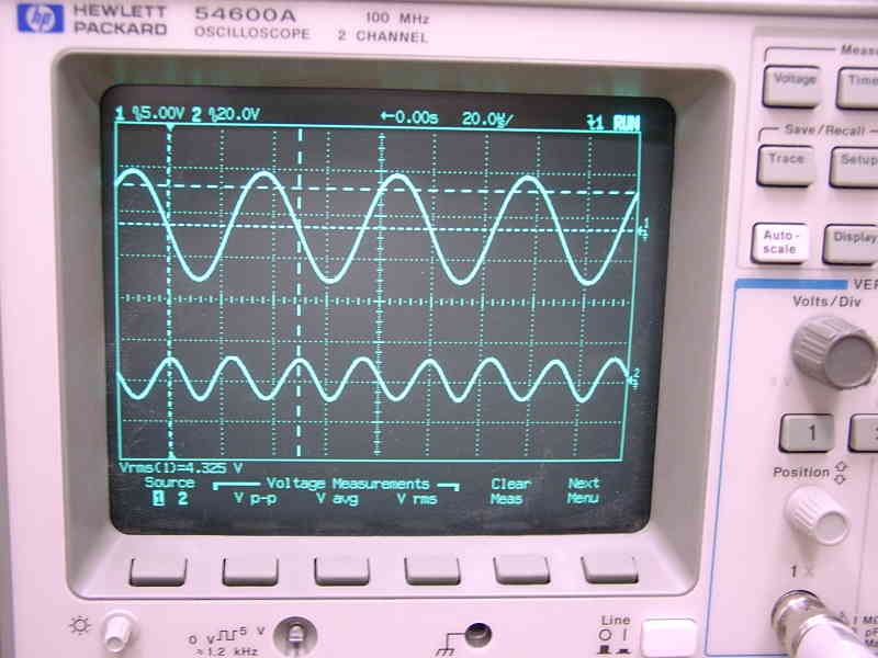
Here's a couple of 'scope traces... the top one is 4.8V RMS into 8 ohms at 1 kHz, showing the signal (top trace) and distortion residual (bottom trace, not same scale). The bottom one is the same thing, at 20kHz. Note that the residual is almost all 2nd harmonic.
This circuit performed better than the tube current source I was playing with earlier (using 2 EL34 tubes), when taking the output off the plate of the lower tube. Of course, that circuit has the advantage (?) of using the current source tube as a cathode follower (SRPP) to get lower Zo.
Next, I may have to buy some decent transformers and try this with a 2A3.... though the EL34 should sound pretty good as well.