Fully balanced (differential) line amp / headphone amp using the Korg Nutube
(Note most photos are hyperlinked to full resolution photos).
I've gotten lots of requests for a balanced headphone amp / line amp using the Korg Nutube. So here it is...
This project is not quite a beginner project like the NuHybrid headphone amp. It's not terribly difficult, but is intended for builders who have some experience. You need to be able to build from the schematic and BOM - I don't plan on doing a detailed manual.
This board implements one channel, so you need two for a stereo setup. It runs off of a +/-15V supply (+/-12V will work too). Using OPA551 output buffers, the board draws about 15mA from the +15V supply, and 75mA from the -15V supply (which also powers the filament). If you are using it to drive low impedance loads (like 32 ohm headphones) you also need to allow for the load current. For 32 ohm headphones an additional 20-30mA is usually enough.
It uses a JFET follower to buffer the signals into the Nutube grid, and either another JFET buffer (for line amp use only) or an opamp buffer at the output. There are a number of build options for attenuation, negative feedback, and buffer components.
Here is the schematic (or download a PDF file):
The fact that the Nutube is directly heated - and that it has a common connection for both triode filaments - means that to implement a classic differential amp, you need to float the heater power supply. That is the purpose of the isolated DC/DC converter. It looks a little odd, but it is sitting on the negative supply rail (-15V), with a 5V LDO in front of it from ground. This generates a ~-10V supply to drive the DC/DC converter with 5V in. The DC/DC converter output (which is isolated from its input) is then regulated to the 1.4V needed to drive the two triode filaments in series.
The filament common lead is connected to a LM334 CCS to the negative supply. The tail current is set to about 95uA.
Since the Nutube is operated in class A2, where the grids draw some current, a buffer is needed to drive the grids. This is implemented with JFET followers. I used Linear Integrated Systems LSK389B dual FETs. You can also use single JFETS (like 2SK170) if you want - the PCB has pad patterns for both the TO-71 dual FET and the TO-92 single FETs. Ideally the single FETs should be matched in pairs.
Bias is adjustable for each triode section individually, to allow matching in case the two sections have different characteristics (though I've not found much difference). The bias is set by measuring the voltage on the plates of the Nutube. There are test points (TP3 and TP5) for this. Set the bias as indicated on the schematic. There are several choices shown for the plate load resistor - you need to adjust to the correct voltage for the resistor used. Note that the gain changes depending on the resistor. Gains between 2 and 5 are attainable without using any negative feedback. Note that the maximum output level also depends on this resistor.
There is also a balance pot that attenuates the inputs slightly. You can adjust this to null common mode gain, if needed. (For normal uses it's really not necessary).
There is the capability to add negative feedback from the plates to the inputs (R10 and R11). I did not use any - I'll leave that to advanced experimenters. There are also resistor patterns at the input and output if you want to add any attenuation.
The plate circuit of the Nutube is high impedance, so it also needs a buffer to drive a load. I have two options on the PCB: you can include another JFET follower (like the one on the input), or use an opamp. If using the JFET buffers, the load impedance is limited - I would not use it to drive anything lower than about 10k. If you use the JFETs, you definitely want matched pairs (or use the LSK389B) because if there is mismatch you will get a DC offset on the output.
The opamp buffer can drive much more current, and is needed if you want to drive headphones or a 600 ohm load. The opamp needs to work on +/-15V, and be unity gain stable. It is a standard 8-pin DIP single opamp. I used the OPA551, which makes a good headphone driver. Note that you want to make R30 and R31 smaller for headphone use - 10 ohms is generally good, but you can use a value that you like. It will change the damping on your headphones. For 32-ohm headphones you may want to go to near zero.
Here is the parts list (BOM) in either XLS or PDF. Most of the parts can be purchased from Mouser. The Linear Integrated Systems' FETs can be found at one of their distributors, NAC semi. They sell small quantities online. I will be selling the PCB through my eBay store.
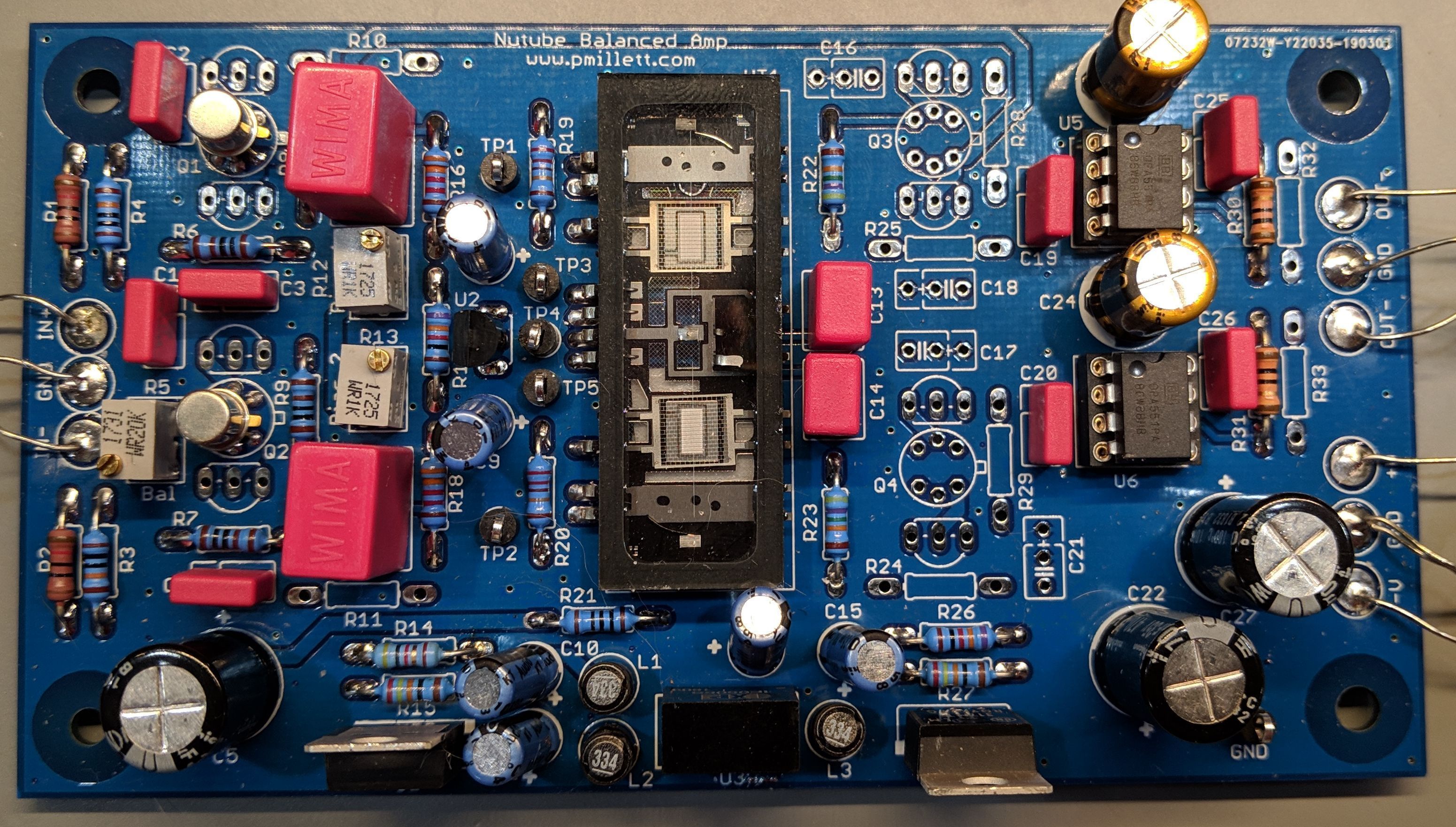
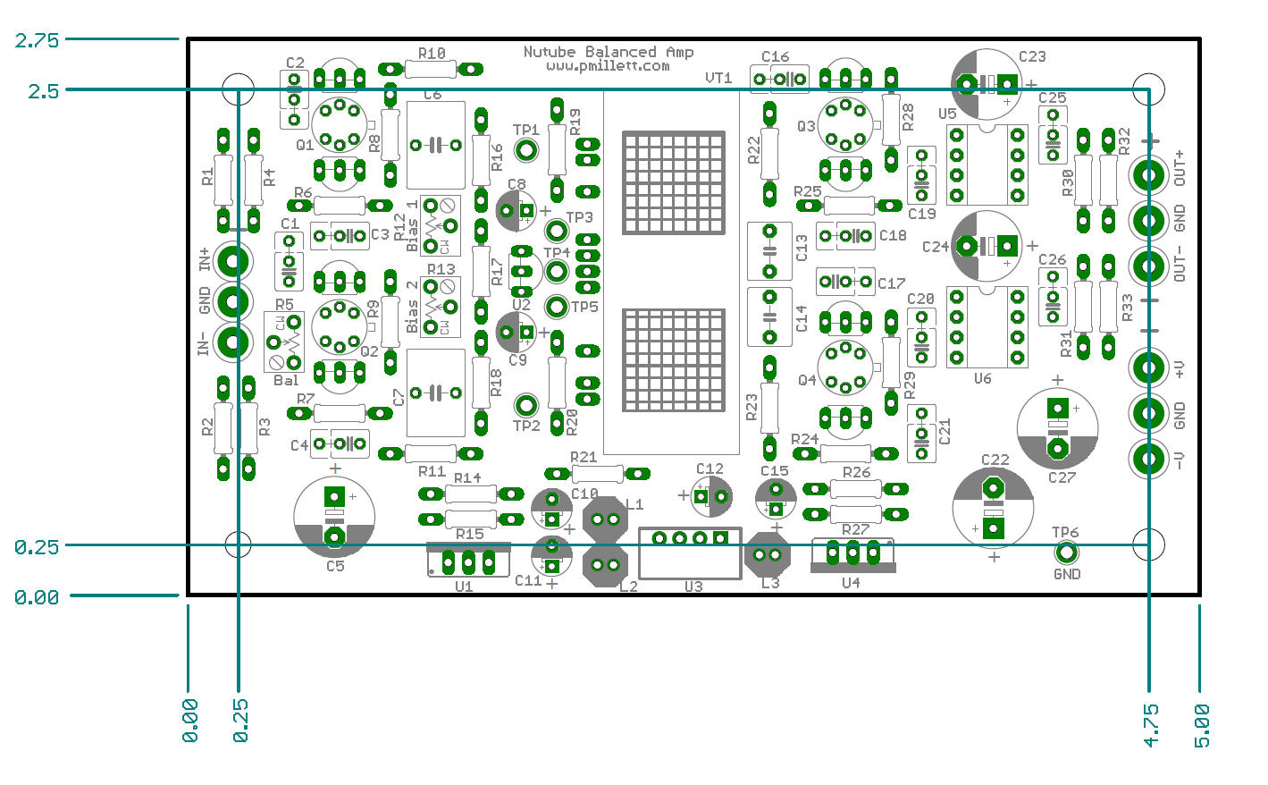
Here is what the PCB looks like (or download a PDF file):
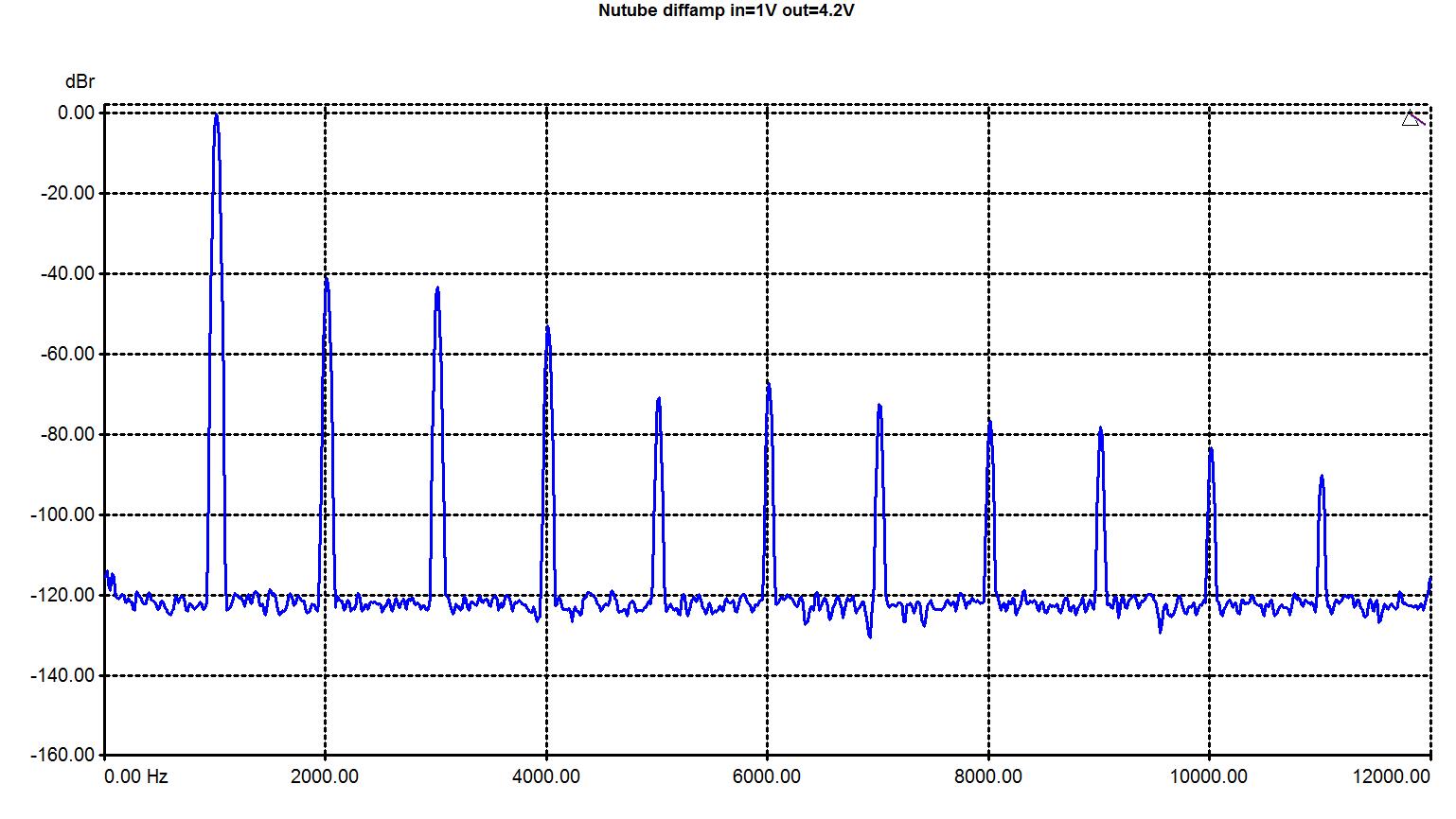
Here are some measurements (taken with mid gain, 221k plate loads - note that things change with bias setting and plate load):
1kHz FFT at 1V in, 4.2V out
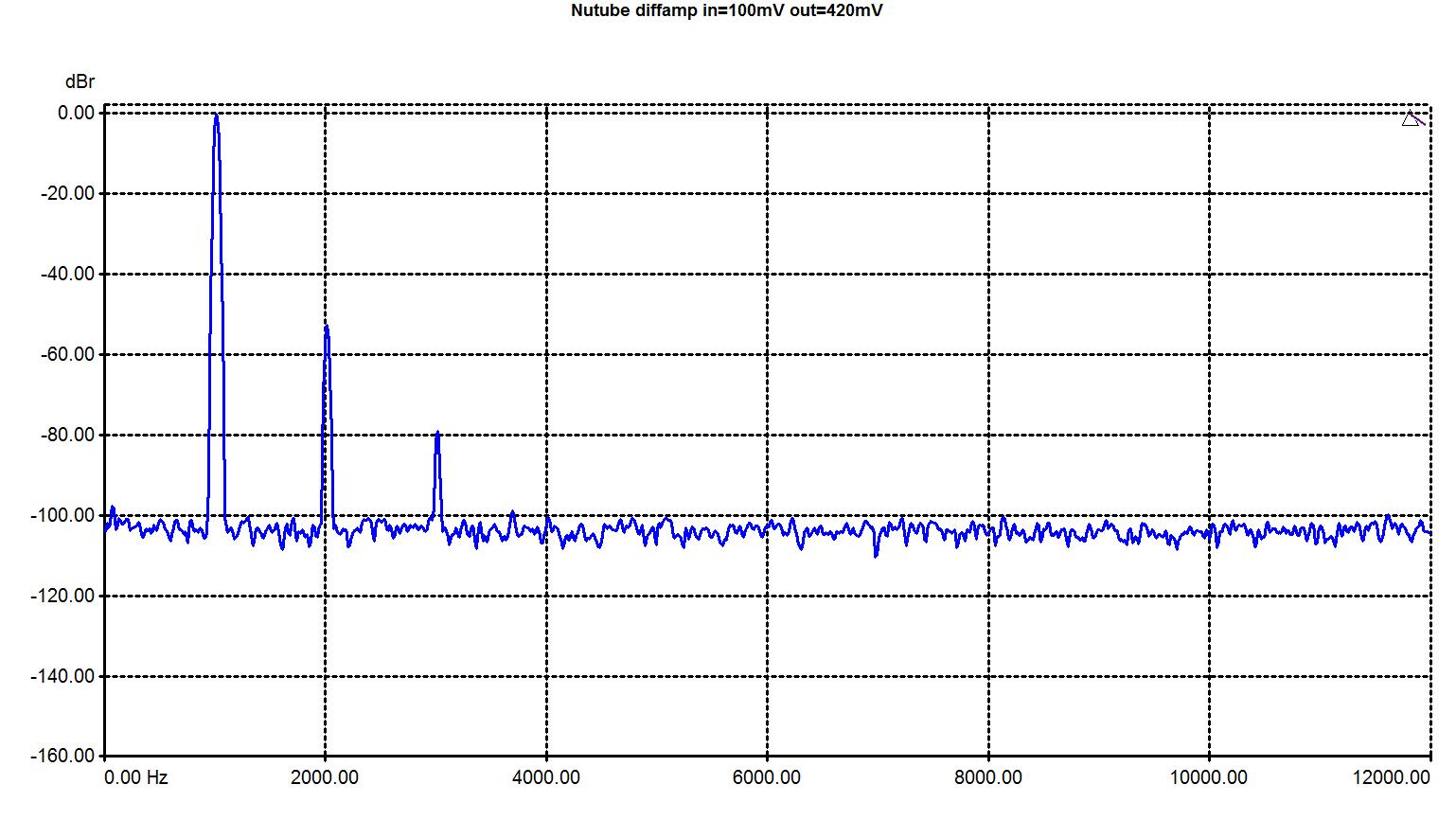
Same with 100mV in and 420mV out (noise floor comes up 20dB because the signal went down 20dB):
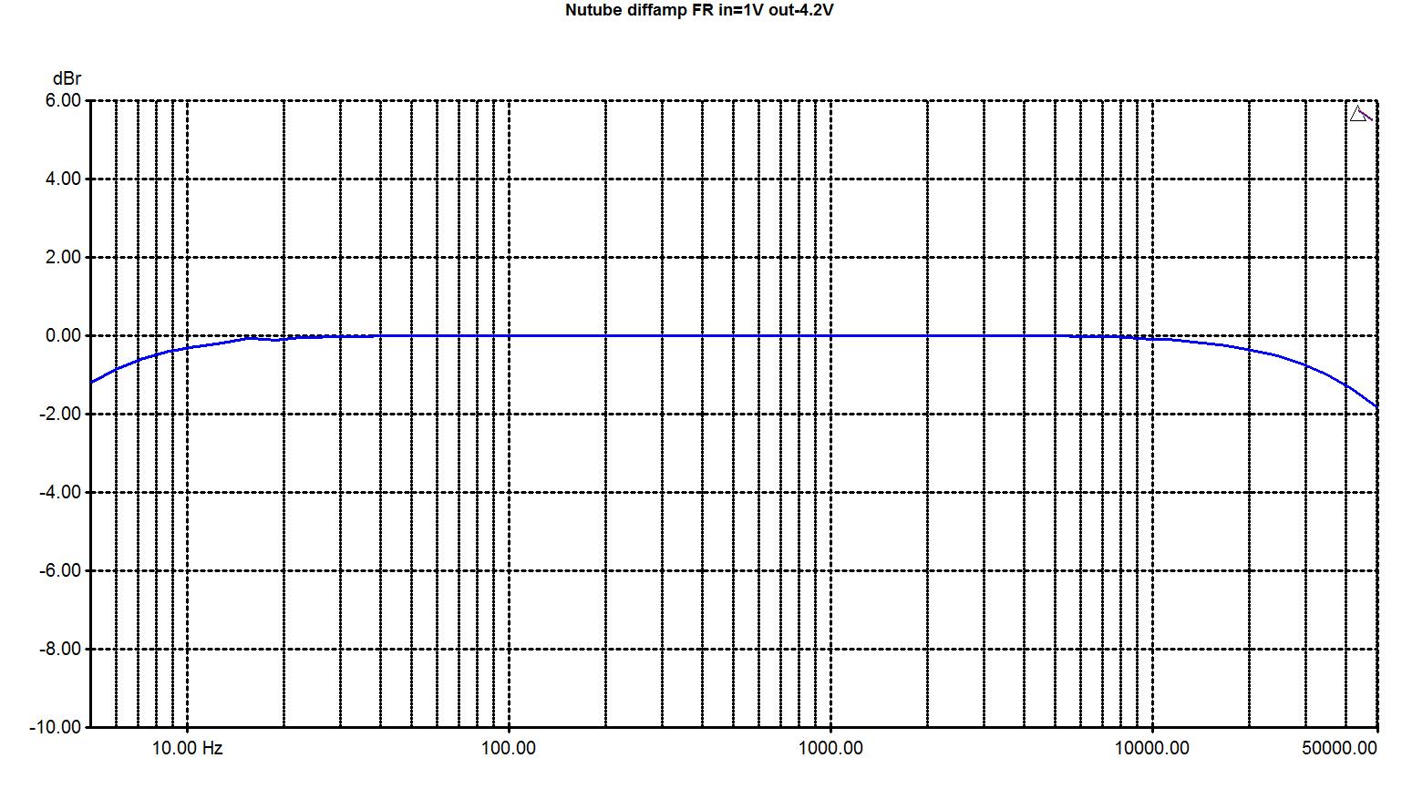
Freq response:
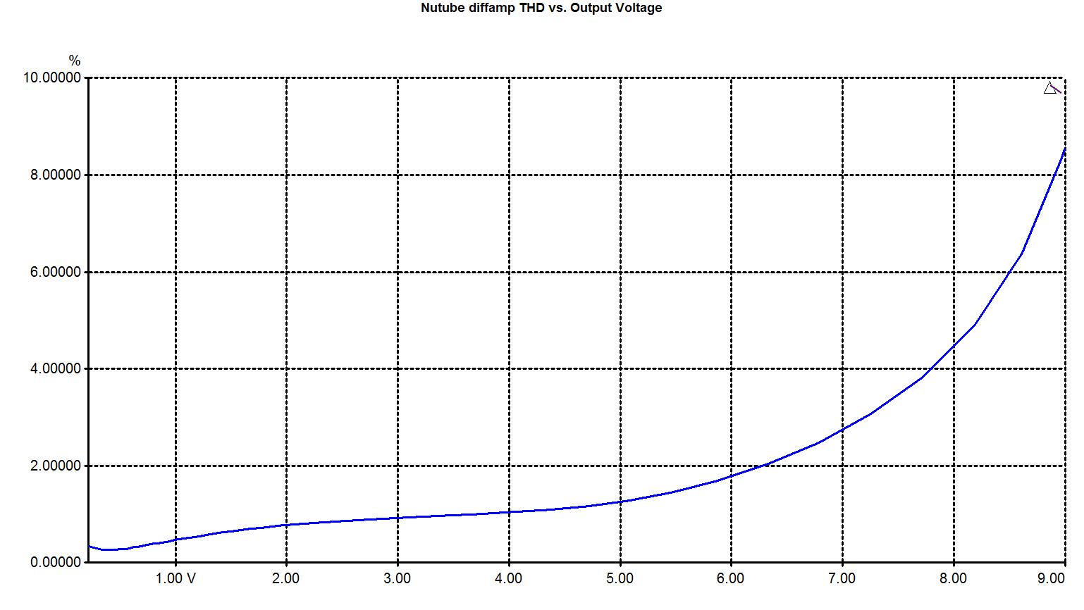
THD vs. Output Level (at 1V where I usually measure headphone amps it's 0.5%):
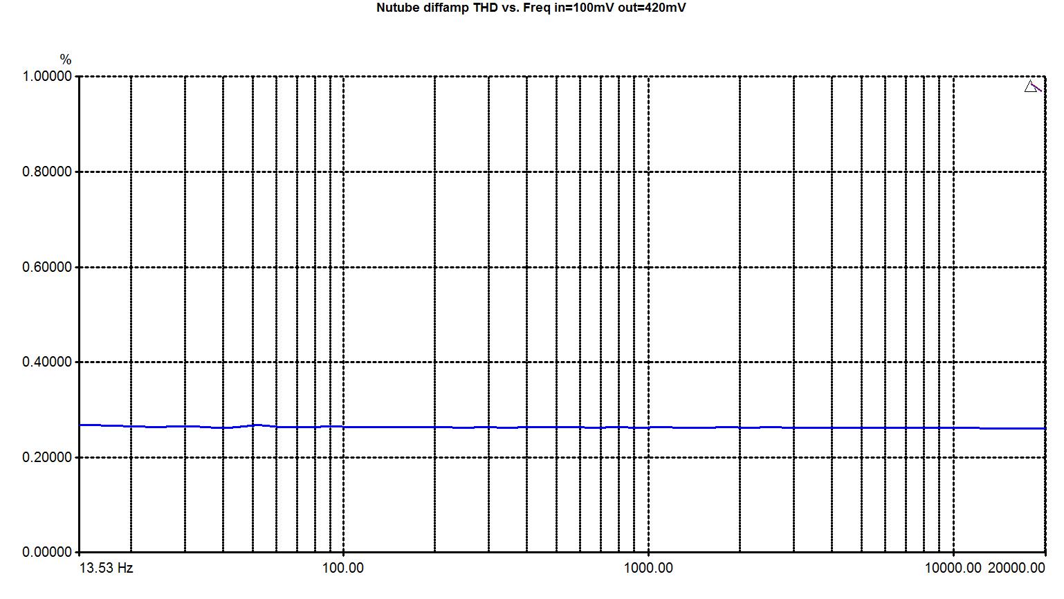
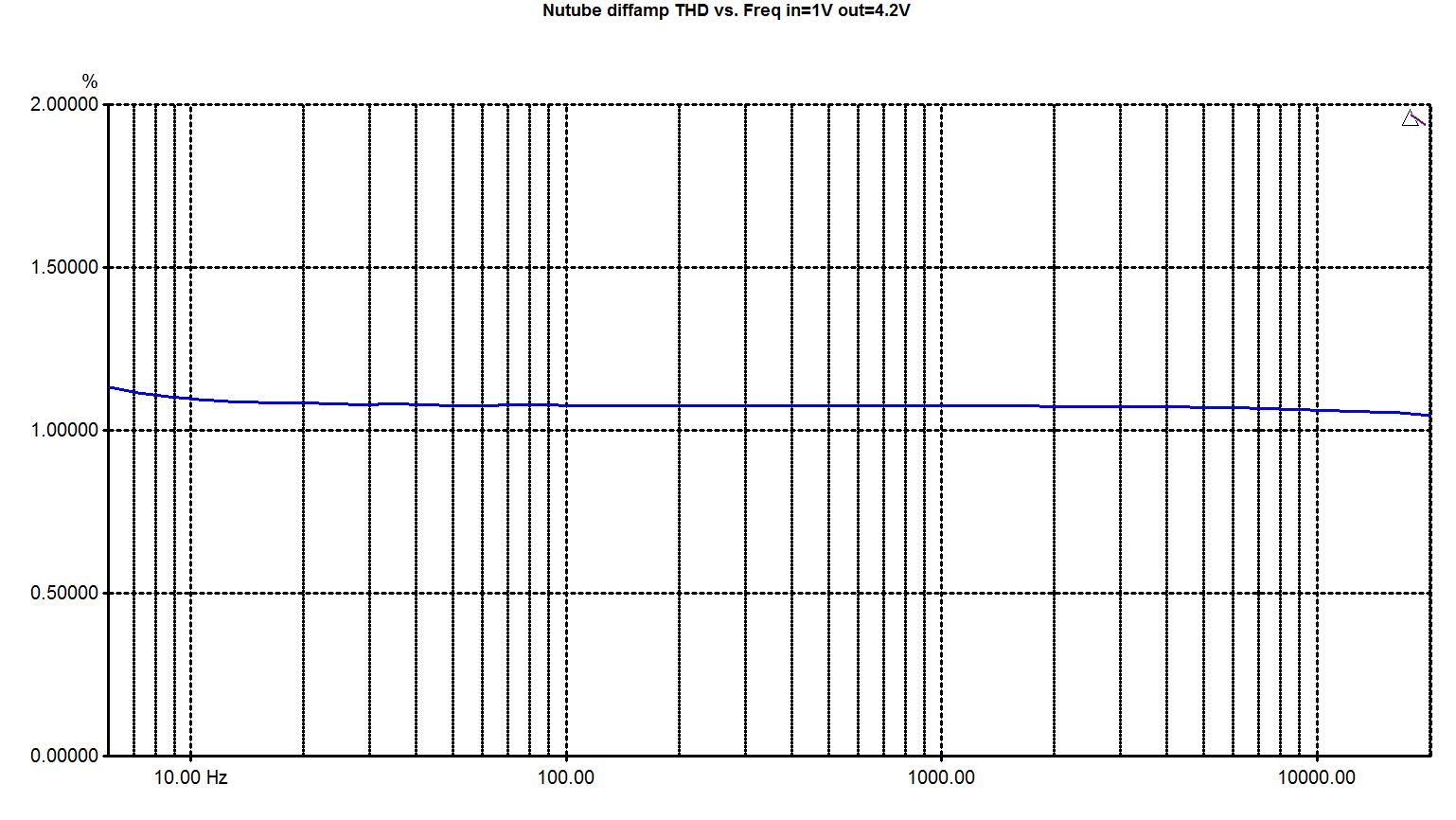
THD vs. Freq @ 1V in:
And at 100mV in: