A big bad high-voltage bench power supply
(Note that the photos are hyperlinked to full-size photos in grisly detail)
I got tired of running into the limitations of my Heathkit IP-17 high voltage bench power supply. I always needed just a little more current.
Commercial high-voltage power supplies are few and far between, and they cost a fortune! So I decided to design and build one.
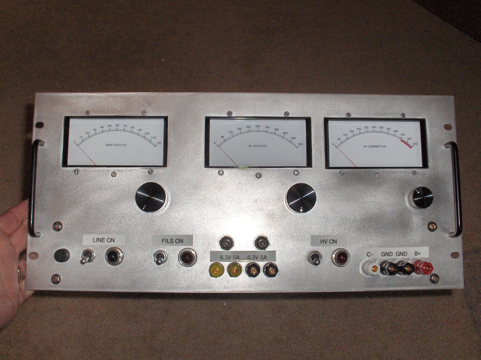
This supply puts out 0 to a tad over 450V, at up to 500mA, adjustable by a front-panel 10-turn pot. It also has a low-current bias output that will do 0 to -120V or so at a few tens of mA, as well as a pair of floating 6.3V 5A filament outputs.
The circuit is based loosely on the IP-17 design, with some influence from other places. Here's what it looks like on paper:
Since this image is probably hard (impossible?) to read... here is the full schematic (PDF file).
The circuit is really pretty simple. It used five 807 pentodes in parallel as the pass element. Why five, and why 807's? Well, I had a bunch of 807's sitting around (actually 5933 / 807W's), and I only had five sockets and top caps. Voilla!
You can also use 6L6's, 12E1's, 6550's, or other similar tubes. Maybe even sweep tubes. The main thing is that they need to be pretty beefy.
Why not triodes, you ask? The benefit of pentodes (with a floating screen supply, tied to the cathode, by the way) is that they can operate with very low voltage drop across them, lower than the big pass tube triodes. Of course you could do this with triodes, but the maximum output voltage would be reduced.
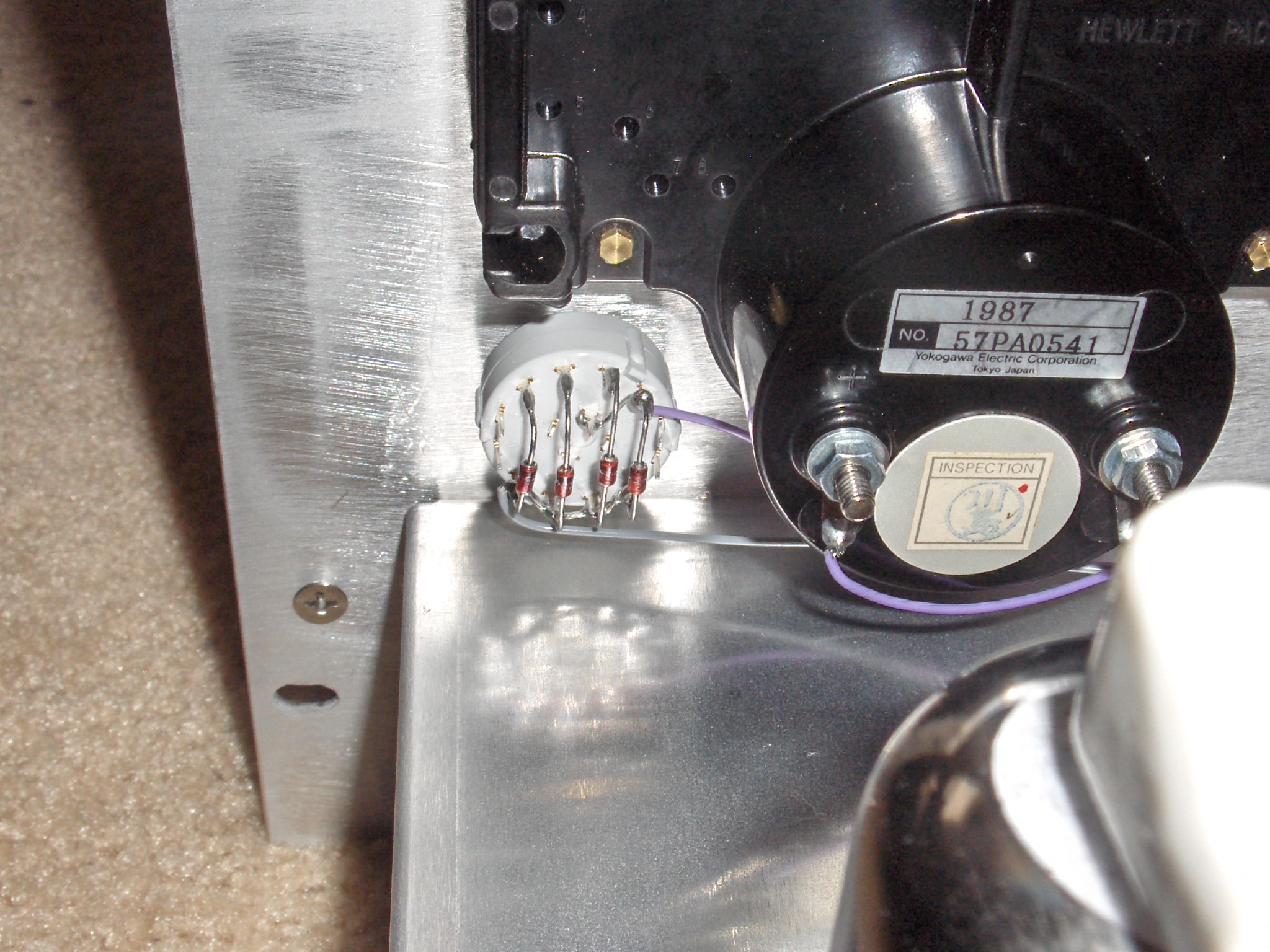
Another side benefit of pentodes is that you can do a simple, brain-damaged half-assed current limit by simply taking advantage of the nearly horizontal plate curves of the pentode. If you limit the grid voltage, you limit the current. So this design has a switch-selectable grid voltage limit (implemented with zener diodes) that gives a crude current limit function. It actually works, too. Here's a close-up of the Ilimit switch and the zeners:
Since I'm cheap, this was basically a junk-box build. OK, I do have a well-endowed "junk box" (more of a room, actually). I used tubes and iron that I had available. I bought a few odds and ends, like some resistors, relays, the chassis, and the panel meters.
See the big blue transformer? It's a power transformer from a Tektronix 535 o'scope. It's perfect for this use because it has a lot of windings, and lots of power. You can find some data on it on my Tek power transformer page.
If you don't have a 535 or 545 lying around to cannibalize (check e-Bay and craigslist, you never know when you might find one nearby - that's how I got mine) and can't find this transformer, you can always substitute appropriately. You will need three isolated HV windings: ~360 VAC @ 500mA DC for the main B+, ~180VAC @ 50mA DC for the floating screen supply, and ~180V @ 50mA DC for the negative bias. This assumes you are doing solid-state bridge rectification as I did; if you wanna use tubes, you'll need to account for that.
You also need several isolated 6.3V filament windings - one for the error amp (600mA) and one for the pass tubes (4.5A). If you want to supply filament power out the front panel as well, you need windings for those too.
There's nothing sacred about most of the components I used. Like the chokes - again, some that I had on hand.
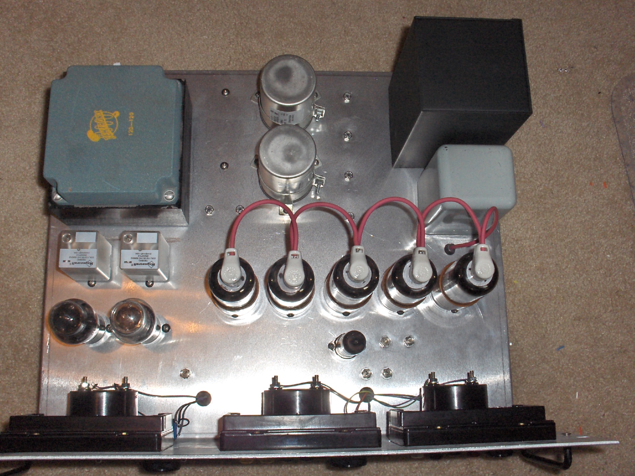
Here's the inside:
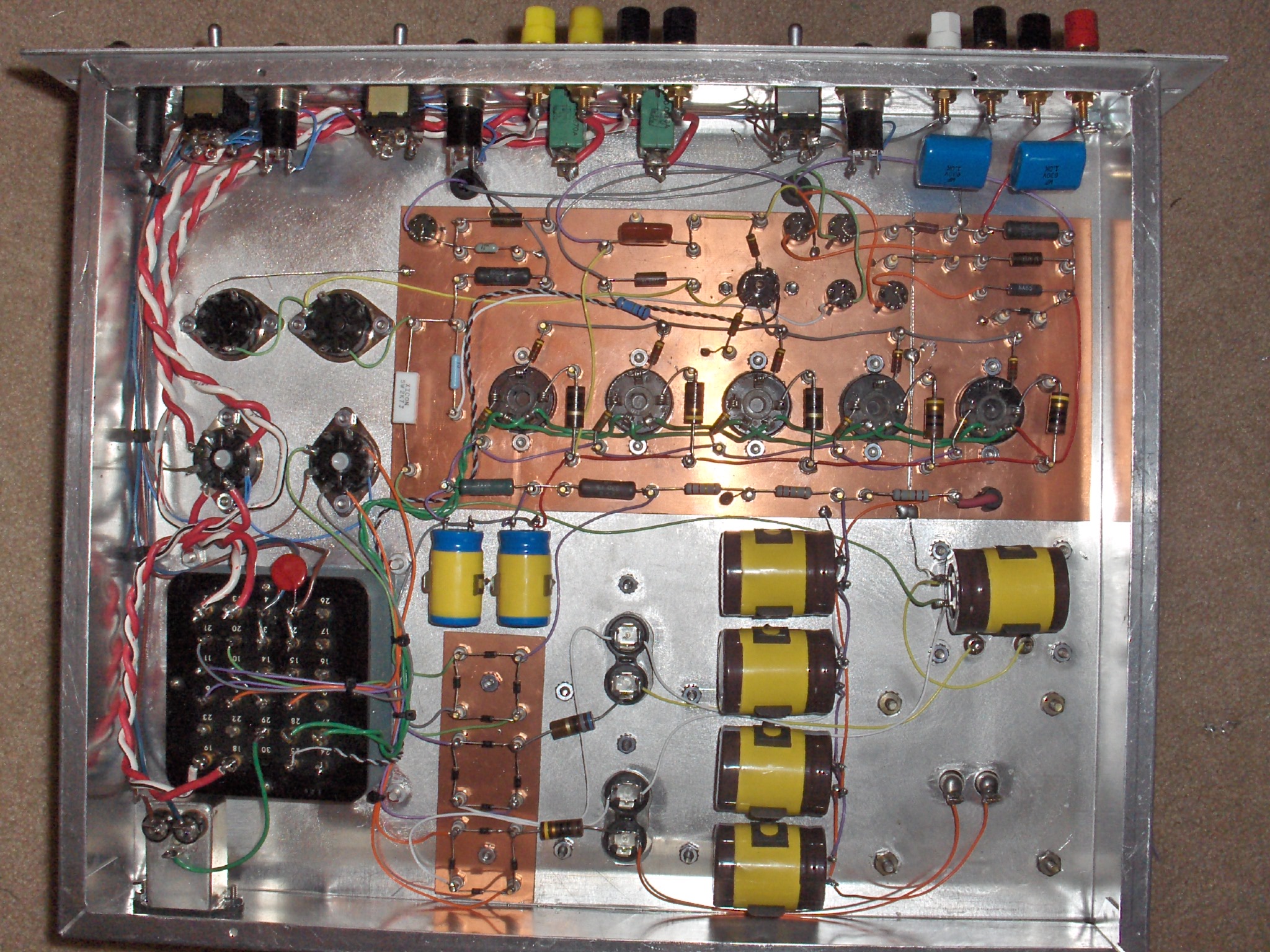
I used my usual single-point terminals on PCB construction.

A few random points:
All the electrolytic caps are mounted to the metalwork with clamps. In some cases the can of the cap is sitting at elevated voltage (~250V) so I protected them by wrapping mylar tape (the kind used in winding transformers) around them. Maybe not necessary, but a good precaution.
I put the rectifier bridges on their own little terminal board as a matter of wiring convenience.
Note the BIG red/white wires. That's the filament power that goes to the front panel jacks. I didn't want to lose much voltage. The windings are rated for 7 or 8 amps - enough to start a fire, me thinks - so I protected them with some panel-mounted circuit breakers (the kind they use in airplanes).
The two octal sockets closest to the power transformer are actually relays. One provides B+ switching (by switching the secondaries of the main B+ and screen supplies), and the other switches the 6.3V filament power to the front panel. It will make sense if you look at the schematic.
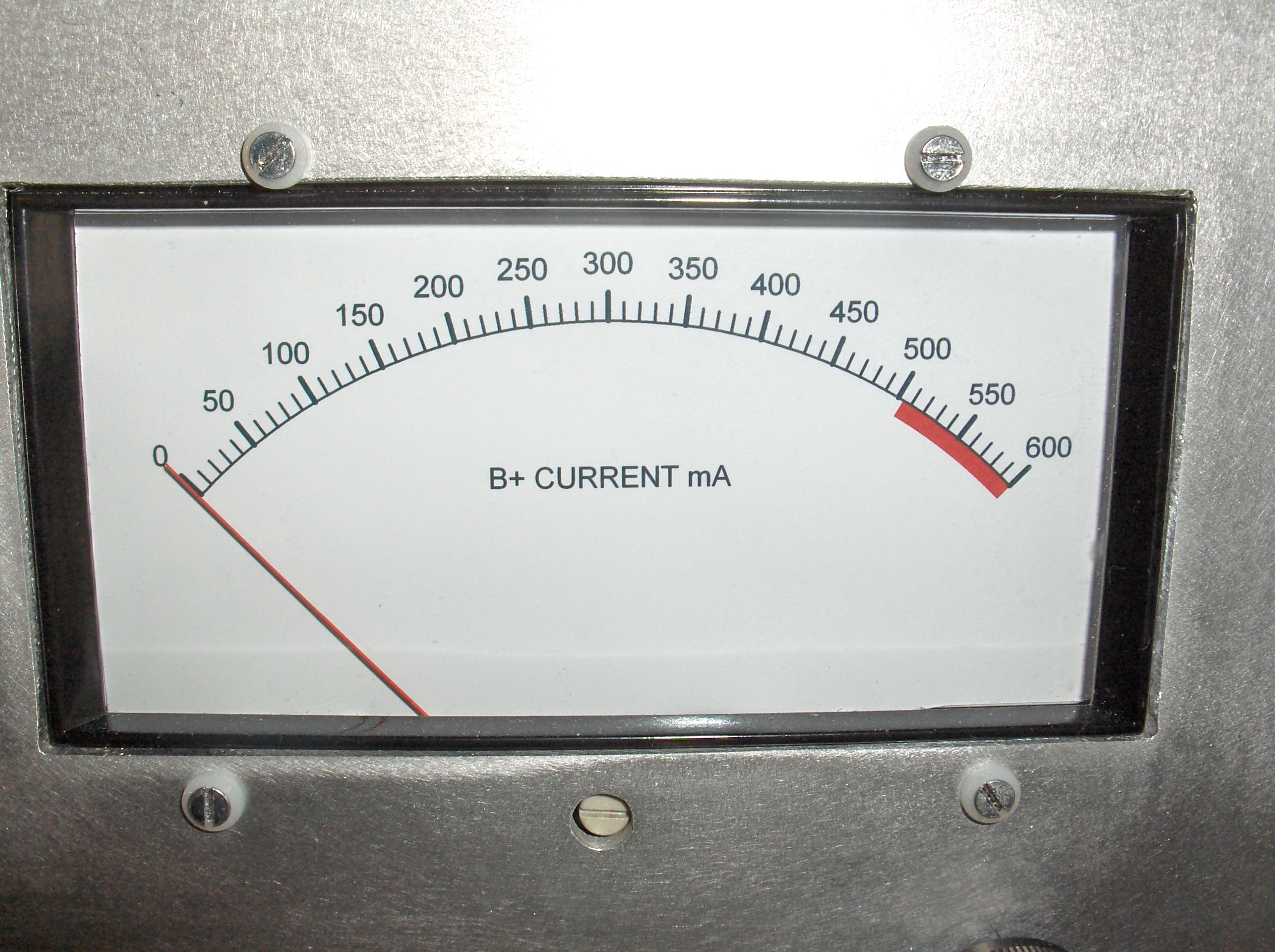
Nice meters, huh? They're actually surplus that I picked up for next to nothing. They were replacement meters for a piece of HP test equipment. The original meter scale had something weird on it, megohms, or microwatts/square millimeter, or something like that.
The meter movement is a standard 50 microamp full-scale meter. I made new scales using a program I found on the Internet called "Meter" from Tonne Software. It took some fooling around to get it right, and then I printed it on photo paper and cut to size, then glues to the old metal meter scale. Way cool!
The monster is built on a 17" x 14" x 3" aluminum chassis, with a standard 6U rack panel (19" x 8-1/2") on the front.
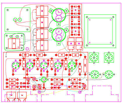
Mechanical drawings (undimensioned, as shown above) are available as well. Here's a PDF version if you don't have any CAD programs.
You can also download a ZIP file that has the schematic (OrCad DSN file and PDF) as well as the mechanical drawing (AutoCAD DWG and R12 DXF files).
Questions? Email me, I'll respond eventually... I promise...
![]()