Isolated Current Sensor for PanelPilot Digital Panel Meters
Normally, when you want to measure plate current, you just stick a small resistor in the cathode circuit, and measure the voltage drop across it. But I'm working on a push-pull amp using the 815 tube. The 815 is a dual beam tube, with a common cathode and G2 connection. The 829B and several other transmitting tubes share this "feature".
I'm using fixed bias, and driving it in A2. So I really wanted to be able to independently measure the plate current through each side of the tube. I was reluctant to put any kind of meter directly in the high-voltage (600V in this case) B+ path. So I started looking at isolated current sensors. Note that this type of sensor works equally well in the cathode circuit.
There are lots of isolated current sensors available, using different technologies, with widely varying price and performance levels. I decided to go with a relatively inexpensive uncalibrated sensor from Honeywell, the CSL series. This is a hall-transducer based, "open loop" sensor, available from DigiKey or Mouser for about $15 each. This particular model (CSLW6B1) gives a DC output of about 1V/A, or 1mV/mA. Current is sensed in a small coil of wire (60 turns) wrapped around a ferrite core, which directs the flux across a Hall sensor element. This introduces a little resistance (160 milliohms) and a little inductance, but it's pretty insignificant in a tube amplifier circuit. Strangely Honeywell does not provide an isolation voltage rating, but looking at the thick plastic bobbin that the coil is wound on, I would thing it's good for more than 1kV. Most line-voltage stuff needs 1500V isolation...
OK, so I found a sensor. It requires a DC supply voltage of 5V. It's also not calibrated in terms of zero-current output voltage and gain; both can vary by ~10%. So I needed to provide a circuit that can allow adjustment of these parameters. Then I can output a calibrated voltage that's proportional to the current through the transducer.
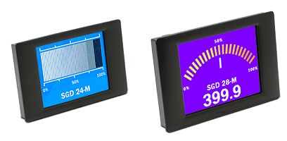
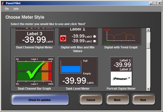
Along the way I started looking at meter options. I thought it would be way cool to have a little LCD display that could be programmed as a multi-function panel meter. I almost started designing such a thing, until I found this:
This family of devices (which comes in a number of different sizes) is made by Lascar Electronics, and is programmed using a free piece of software called PanelPilot. You can see compatible products (which come in a number of sizes) on the PanelPilot site. A cool interactive demo explains the features.
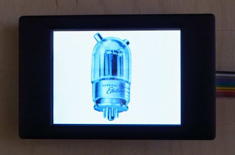
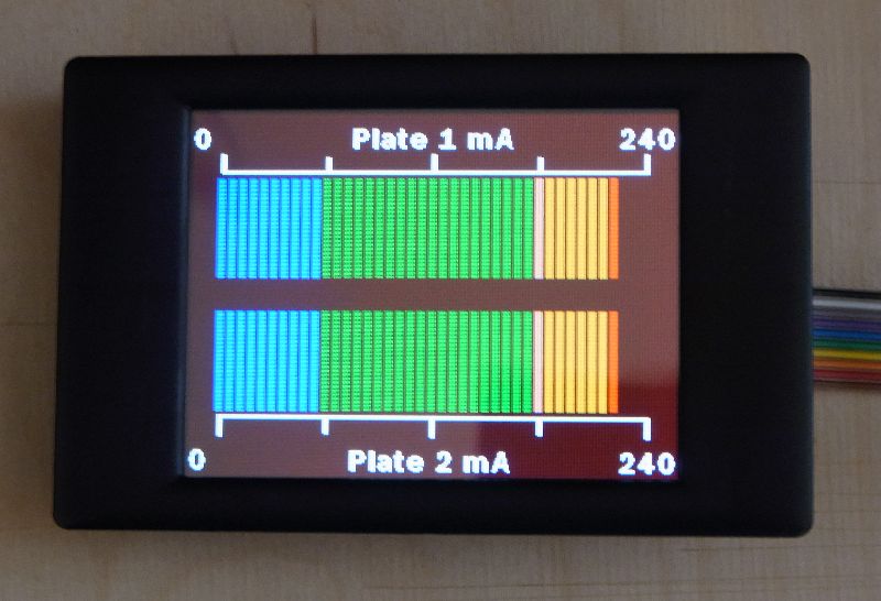
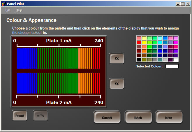
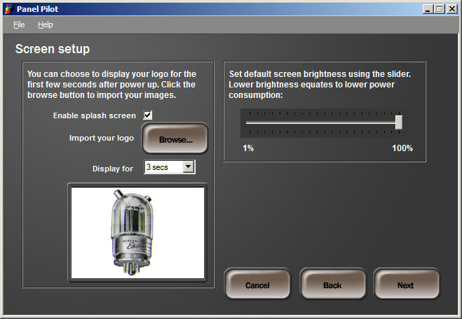
You get to choose the display presentation, colors, scaling, text, labels, and even download a splash screen image to the meter! One or two inputs are supported, so in my case, I used two channels to display the plate current for each side of the 815 on one display:
The PCB
To implement all of this, I designed a PCB (are you surprised?) to implement 2 channels of isolated current sensing plus the power supply for this and the PanelPilot meter. The PCB connects to the meter with a 14-pin ribbon cable.
Here's what the bare and assembled PCB looks like:
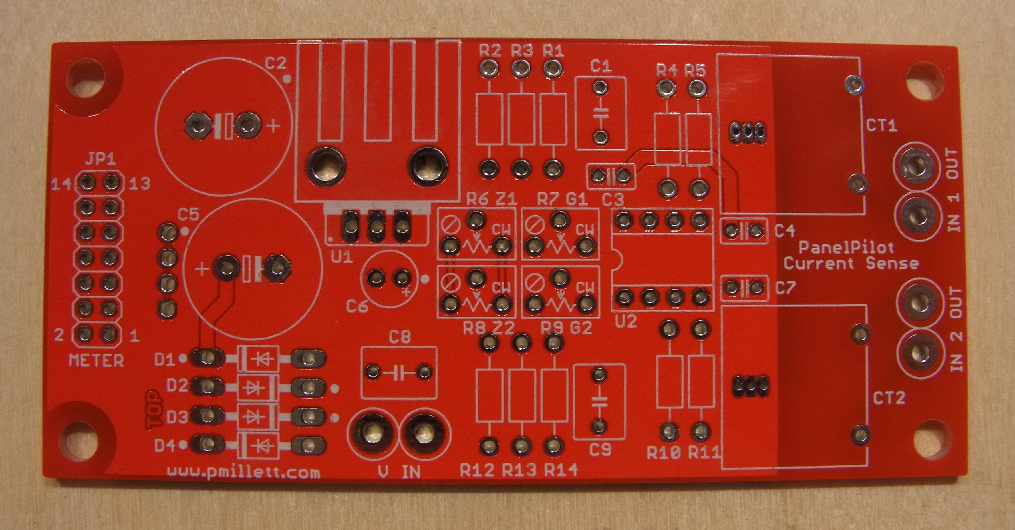
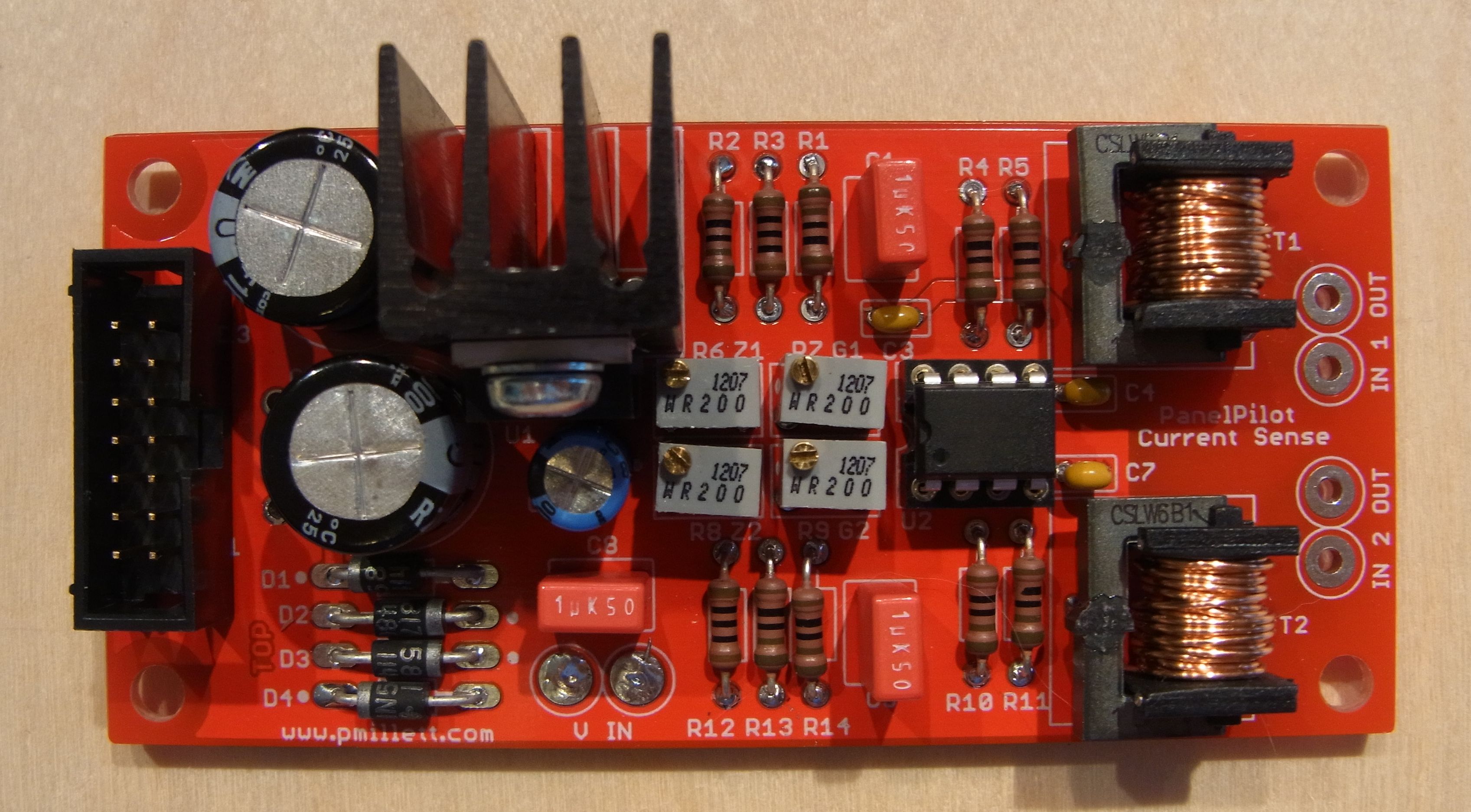
(Don't follow this picture to assemble the PCB - I changed some values. Refer to the schematic and BOM below).
You can find the PCBs on eBay by clicking here.
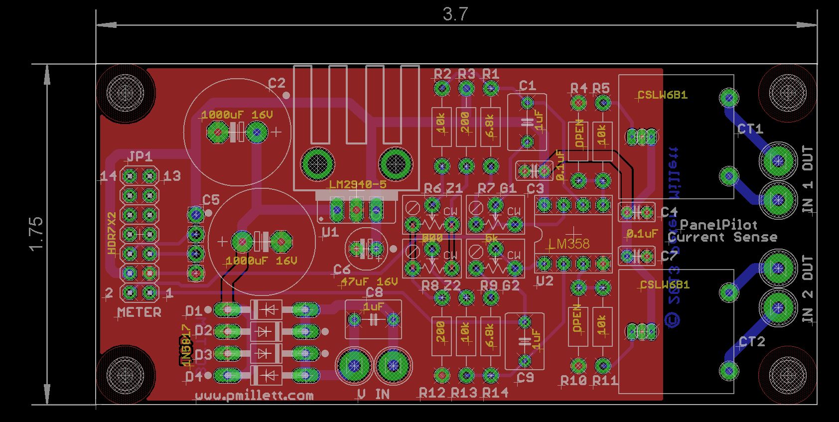
Here's the schematic (or download a PDF version), and a screen shot of the PCB:
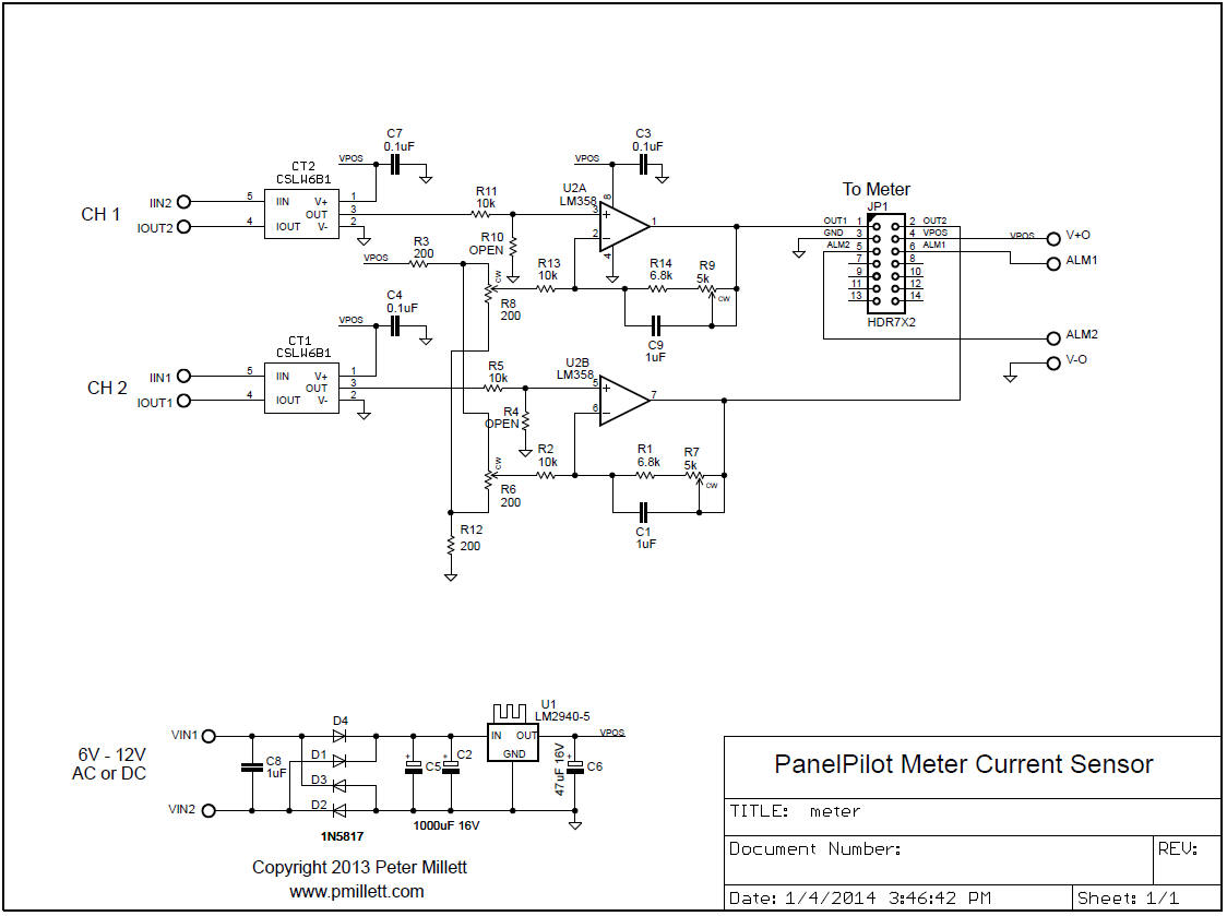
All parts can be gotten from Mouser. Here's the BOM in PDF or XLS format.
Programming
OK, so you build the board... then what?
Before this thing is useful, you need to create the setup for the meter on a PC. This is done using the free PanelPilot software. You then need to download your meter programming into the meter, using a USB cable connection from the PC to the meter. The software is pretty self-explanatory, and the PanelPilot website should give you enough info to do this.
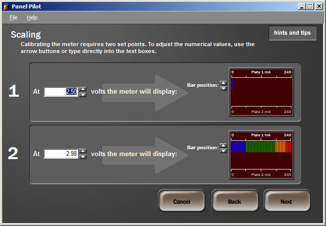
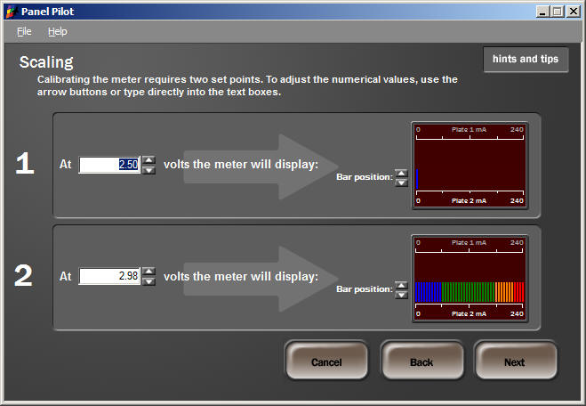
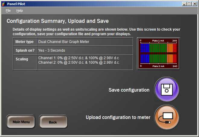
If you are using my PCB as designed above (same opamp gain and current sensors), you need to program the "zero" location to be an input voltage of 2.5V. The "full scale" position is calculated as 2.5V + (2 * FS_A), where FS_A is the full scale current in amps. In my example, full scale is 240mA, so this gives you 2.5V + (2 * 0.24A) = 2.98V.
To get you started, here is my programming file (ZIPped .cfg file). you can load this into the PanelPilot software and look at it, and modify it as you wish.
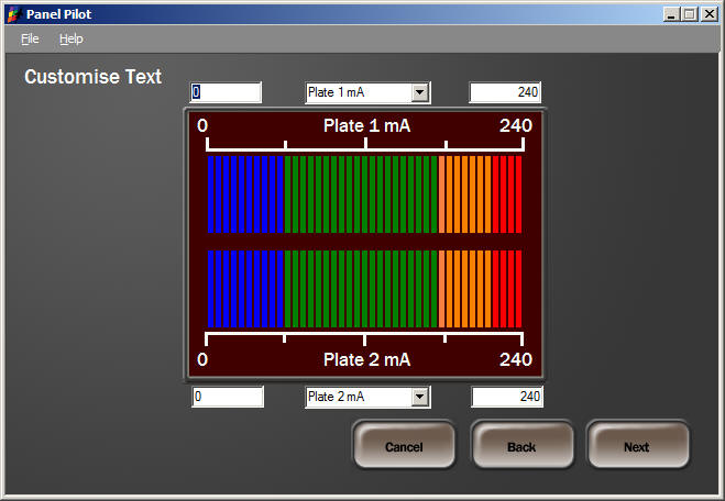
Just in case you get confused, here are screenshots step-by-step for my configuration:
Connections
The current to be measured is provided to the pads labeled (arbitrarily) "IN" and "OUT", one each for each channel. It turned out that the "OUT" side is positive... so if you're sensing plate current, connect "IN" to the plate, and "OUT" to the output transformer. If in the cathode circuit, connect "IN" to ground (or cathode bias) and "OUT" to the cathode.
You need to supply power to the PCB. I power it with 6.3VAC filament power used elsewhere in the amp. You can provide anything from 6V up to ~15V, AC or DC, to the board. It's OK if it has some DC bias on it, since the whole thing is isolated from the rest of the world, so if your filament supply is biased up a bit, no problem.
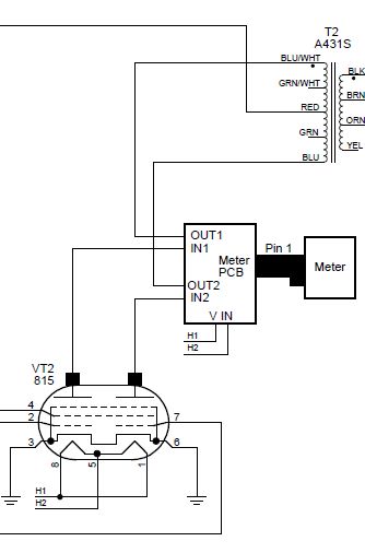
Connect the PCB to the meter with a ribbon cable, observing the pin 1 location!
Here's an example of the connections to the tube (in this case in the plate leads of an 815):
Calibration
Once you have the PCB assembled, it needs to be calibrated. This is easiest to do outside the amp on a bench, though one could do it in the amp if you had to.
To calibrate the circuit, you need a known current. If you have a bench supply with a current limit, you can just short the output and adjust the current to whatever your full-scale meter current is going to be. If not, you can use a battery and a resistor. Measure the current using a DMM in series. So you form a loop of battery - resistor - DMM - current sensor PCB. Use a resistor that gets you close but not over the full scale reading you want on the meter. For example, for 100mA full scale, you could use a 1.5V battery and a 15 ohm resistor to get a 100mA current. But check it with a DMM - the battery voltage may not be exactly what you think it is!
Apply power to the PCB (6V-12V AC or DC), with nothing connected to the current sense inputs. The meter will power up, display the splash screen (if so programmed), then your meter face. Adjust the "Zero" pots (R6 and R8) until you have a few bars showing (or the meter is just above zero), then turn it until the meter just hits the zero point. Repeat for the other channel, then repeat again (there is some slight interaction between channels).
Alternatively, you can use a DMM to set the output voltage (pins 1 and 2 to the meter) to the meter to exactly 2.50 volts.
Next, apply the full-scale current to the inputs. Note if you want you can connect them in series and set them at the same time. Adjust the FS pots (R7 and R9) to get a full-scale meter reading.
You then should go back and repeat the zero settings, and the FS settings, one more time. Then it is ready for use. Happy metering!
Advanced Topics
If you want to sense very large or very small current, you may want to use a different current sensor. The CSLW series has devices designed for between 200mA and 40A full scale.
You can change the gain of the opamp circuit by changing the feedback resistors and gain pots, R1/R14 and R7/R9. Keep in mind the limitations of the opamp used - if you want to drive very close to 5V, you need a true rail-to-rail opamp.