NEW 3/20/26 - I revised the PCB to use a new heatsink (Fischer instead of Assman) due to supply issues. The BOM has been updated. The new PCB is also gold instead of tin
I've considered building a general purpose CCS board for a while. I finally got around to it.
I created two versions: The first uses cascoded depletion MOSFETs, and the second uses a JFET as the lower device, for lower noise in low current applications.
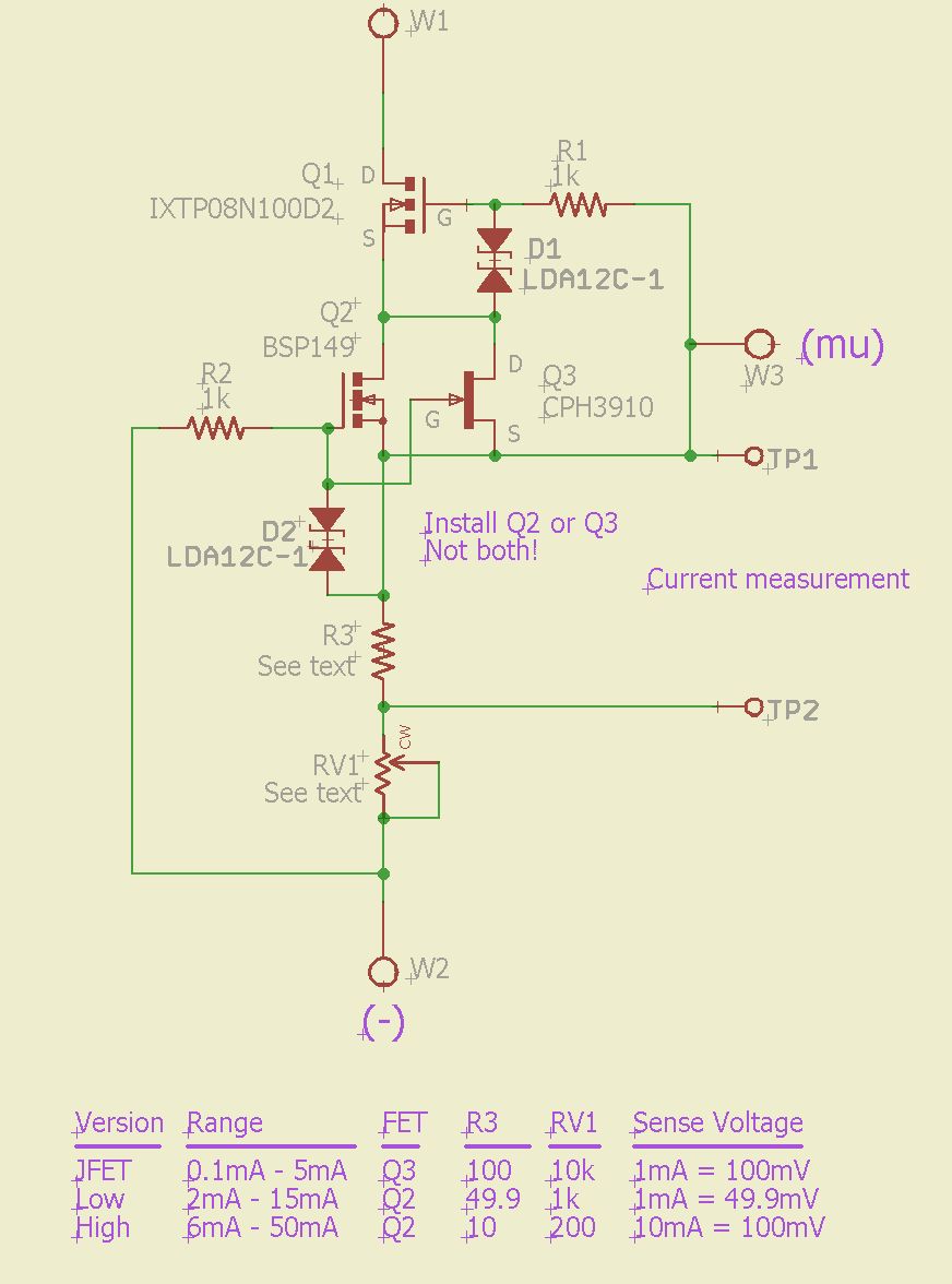
The design is a conventional cascode CCS using a depletion mode MOSFETs as the upper device, and either another depletion MOSFET or a JFET as the lower device:
You can download a PDF schematic here. Here is the parts list (BOM), in PDF or XLS form. Obviously if you build this yourself you are free to use different MOSFETs.
I have specified three current ranges. one for the JFET version and two for the MOSFET version. Different current ranges use a different resistor (R3) and a different trimpot (RV1). Adjustment at the high end of the range is touchy, so if you want precise adjustment you might want to increase R3 and decrease RV1 once you find the center value you want.
The measured minimum voltage (dropout voltage) is about 2-3V. There will be variation from unit to unit, so I would recommend allowing at least a 5V drop across the CCS. Maximum voltage is set by the breakdown voltage of the upper MOSFET - 1000V in this case.
I placed special low capacitance bidirectional TVS devices from gate to source of the FETs to protect them from failures due to power-up (and other) transients.
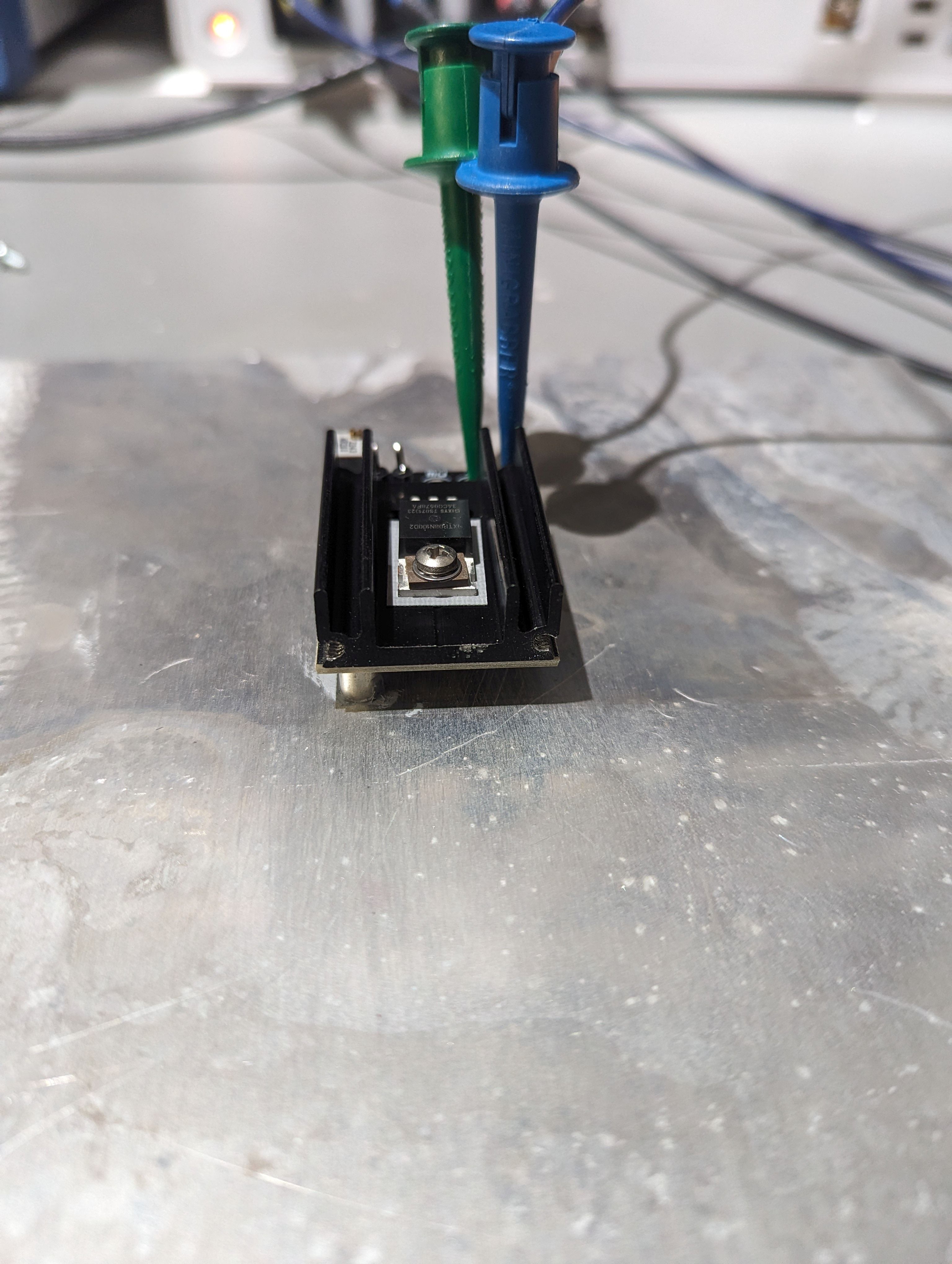
I wanted to make this as compact as possible but still capable of dissipating some power. My solution was to make a small board that is mostly covered by a heatsink on one side, and used surface mount parts on the back side.
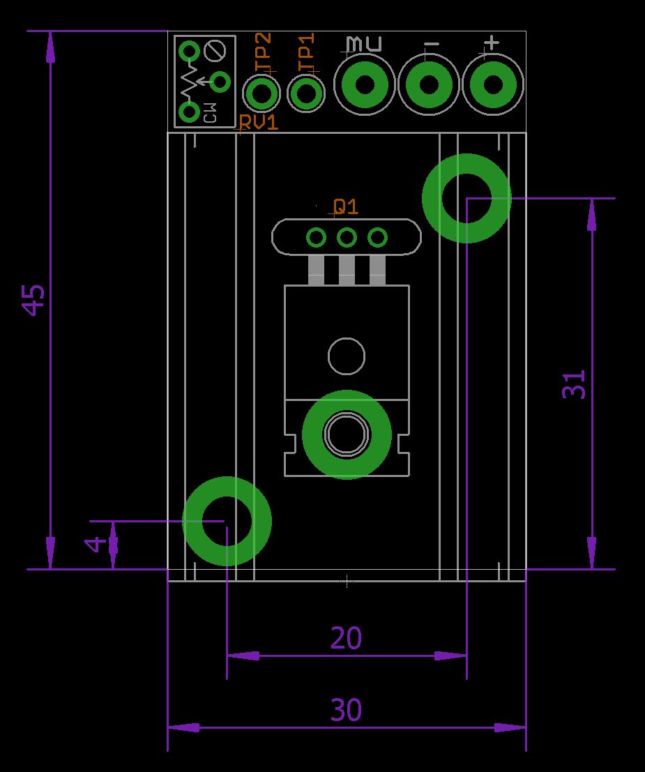
Here's a detailed drawing (or download a PDF of it, or an AutoCAD drawing):
Performance
I made some measurements to see what the impedance of the CCS is.
Ideally, a CCS impedance (resistance if you prefer) would be infinite - that is, the current would not change regardless of applied AC or DC voltage. In reality, even though the impedance of a cascode CCS is quite impressive at DC, capacitances cause it to drop at higher frequency.
Here is the test setup I used to measure the impedance:
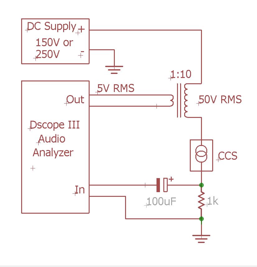
Here's what the impedance looks like for the JFET version, running at 5mA with 50V AC RMS plus 150V DC across it:
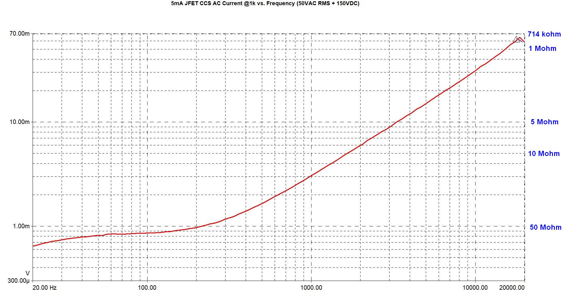
Not a lot of difference with DC voltage. This shows 150VDC and 250VDC for the JFET CCS:
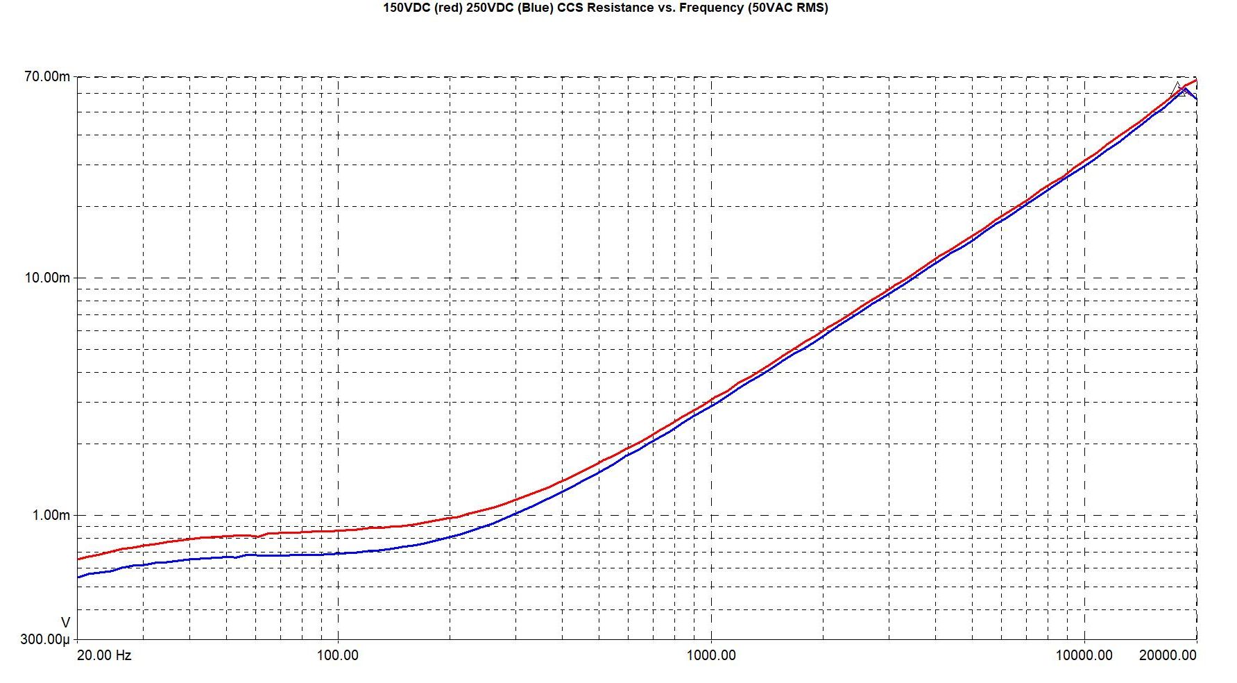
MOSFET CCS at 10mA, 250VDC + 50V RMS AC:
You can see the impedance behaves as expected, dropping at high frequency to about 700-800 kohms at 20kHz. That corresponds to a capacitance of something like 11pF. I don't know why there is a little bump at 20kHz in many of the measurements - probably a measurement artifact, or a transformer parasitic.
Interesting that the MOSFET CCS has higher resistance at low frequency. I am guessing that's because the MOSFET has higher gm than the JFET. At higher frequency the resistance is limited by capacitances, but at DC and low frequency it is limited by the device gain.
Some people have gone through immense effort to make a CCS that has higher impedance than this. I think that's a waste of time. Think about it: A typical triode might have a plate resistance of 10k, Compared to that, a 700 megohm load is irrelevant. It may as well be infinite.
Evan with a high rp tube like a 12AX7, with a plate resistance of 70-80k, the CCS impedance is >10x the plate resistance at 20kHz (and 200x at 1kHz). That is still a nearly flat load line.
Power Dissipation
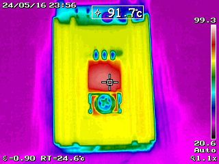
The amount of power that the CCS can dissipate depends on how it is mounted, and also how tolerant you are of heat. Technically the MOSFET allows a junction temperature of 150° C. That is really hot, and I wouldn't recommend going that far. Personally I'm OK up to a case temperature of 100° C.
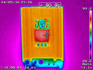
Sitting on the bench at room temperature (25° C) and not mounted to anything, the CCS
can dissipate about 2.5 watts without getting too hot. The case temperature here
is about 90° C.
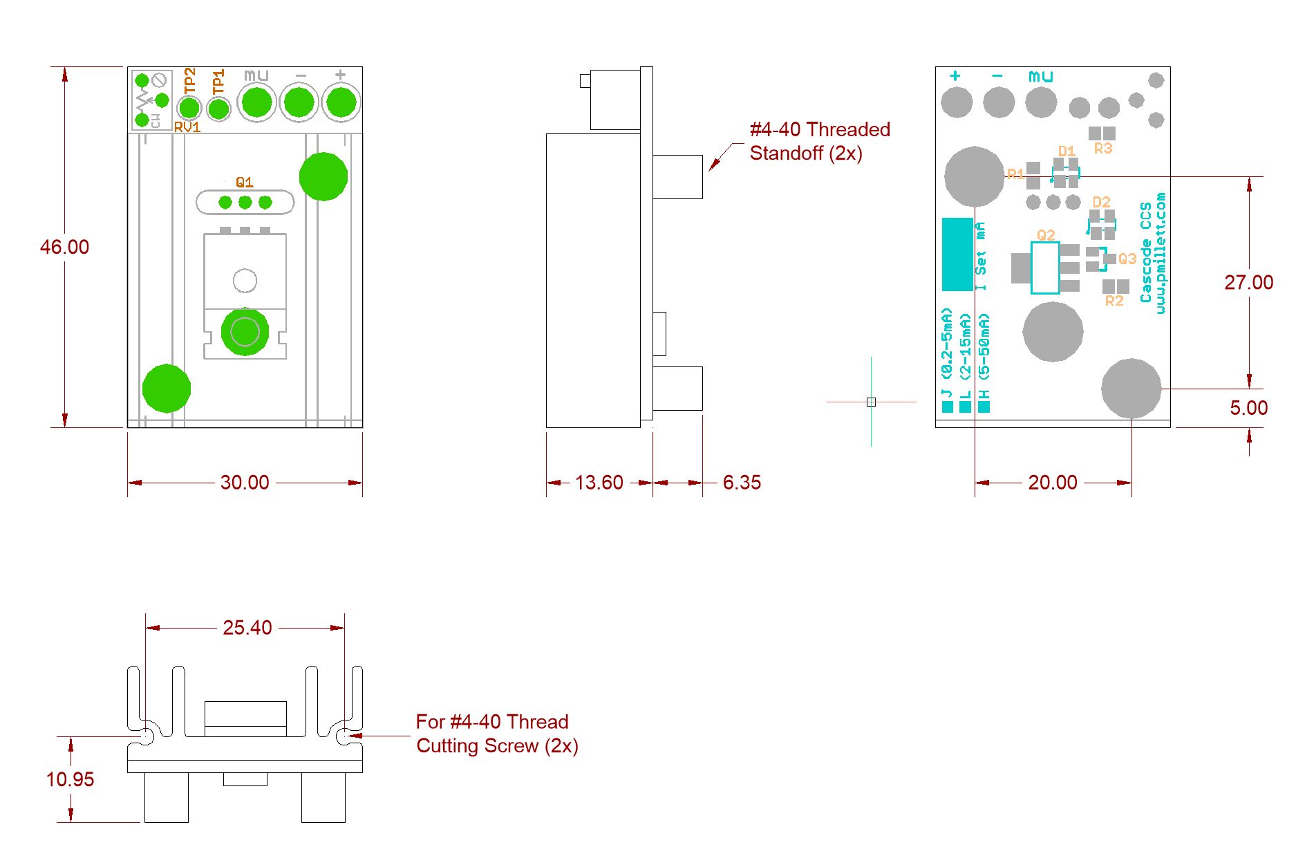
However, I designed this thing to be mounted to a chassis in a couple of different ways. There are holes in the end of the heatsink so that it can be bolted to a chassis. Ideally you should use at thermal pad or thermal grease to ensure good heat transfer to the chassis. #4-40 thread cutting screws should be used.
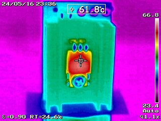
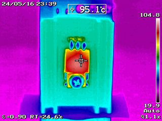
This allows much more power to be dissipated. Mounted to a 7" x 8" aluminum sheet to simulate a chassis (using two #4-40x3/8 thread cutting screws and a thermal pad), you can dissipate at least 10 watts with a 95° C case temperature. 5 watts gives a 62° C case temperature.
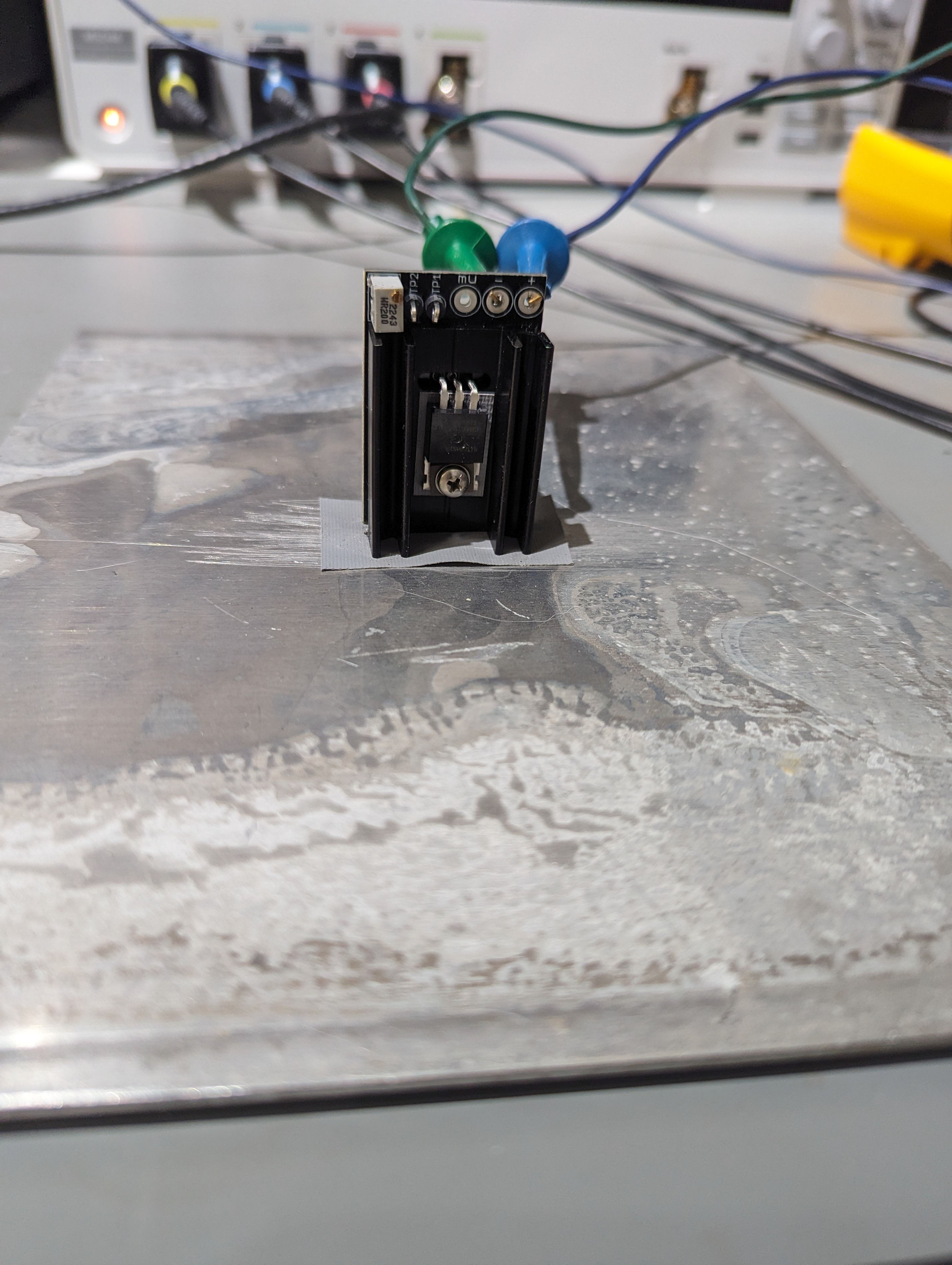
You can also mount the CCS flat to a chassis, using two #4-40 threaded standoffs that are soldered into the board. It's not thermally as good as mounting to the heatsink, but there is some heat transfer through the PCB and standoffs. So you can dissipate about 5 watts mounted this way, with the case temperature 92° C:
If you are building this yourself, I also show an alternate smaller (and cheaper) heatsink on the BOM. If you don't need to dissipate more than a couple of watts and can mount the CCS flat you can use that one.
If you need to dissipate even more power, you'll need to figure out a way to mount the MOSFET on end and bolt it to a bigger heatsink.
General Notes
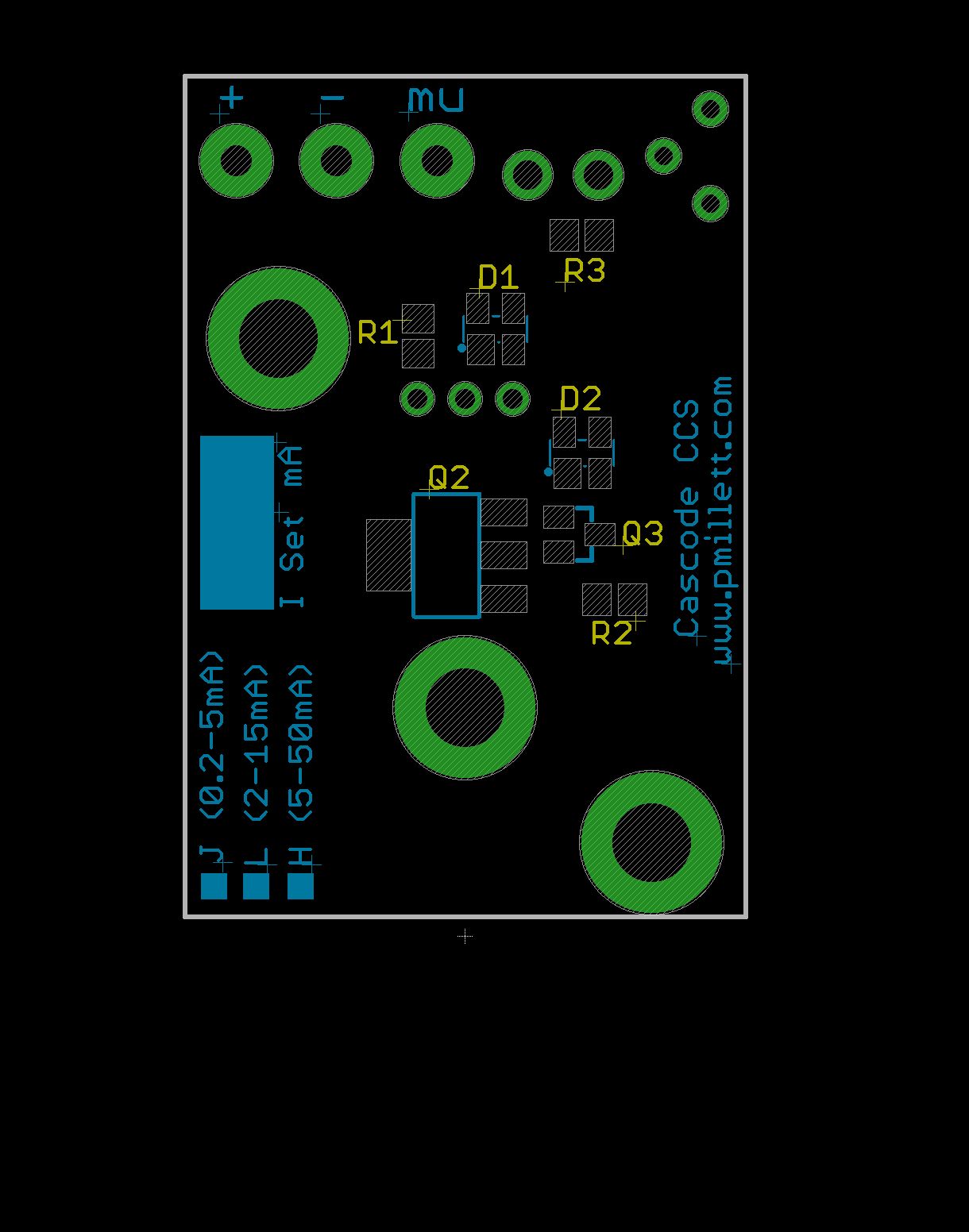
I know a lot of people don't want to do SMT soldering. So maybe against my better judgment :) I will sell these as assembled units, as well as selling bare PCBs.
I'll sell assembled units on eBay, in two different current ranges for MOSFET CCS' and a single lower current range for JFET CCS. If you tell me your desired current setting when ordering I can preset the CCS to that current. Otherwise I'll set it to 1 or 10mA and you can change it as you like. I'll supply appropriate screws for mounting with the completed CCS units.
If you are OK with SMT soldering and are happy to build your own, I'll sell the bare PCBs in 4-up arrays on eBay. I didn't use any really tiny parts (SOT23 and 0805 are the smallest) and no buried pads, so it can be assembled using a soldering iron (no need for reflow). Individual boards are V-scored so you can snap them apart.
The lower MOSFET is in the SOT-223 (TO-261) package used by Infineon and Ixys. The JFET is in a SOT23. In general source and drain terminals are interchangeable on JFETs, so as long as the gate is on the side of the package by itself you should be OK.
Make sure that you use an insulating pad and shoulder washer to mount the TO220 MOSFET. Otherwise it likely will short to your chassis.