
NEW 4/9/2024 - I redesigned the interface to get rid of some difficult to source (and expensive) components. I will leave the old section as it was below.

As mentioned above... this is an updated design of the "Sound Card Interface". Changes included replacing the RMS converter with a more available and cheaper part, replacing the LCD display with one more readily available (and cheaper), and changing the rotary switch to one that is much cheaper and hopefully readily available.
Here is the updated schematic (or download a PDF):

Here's the new parts list (BOM) in .XLS or .PDF format.
The display is from Lascar and is readily available worldwide directly from them. It is connected to the PCB with a simple right angle connector:

I'll sell the boards on eBay along with the plastic front and rear panels:

I am not really happy with the fit of the front panel, especially with regard to the LCD bezel. Be aware you may have to futz around with it and maybe an xacto knife to get it to sit flat. Maybe the beat approach is actually cut off the two pegs on the bezel completely, and attach it to the panel with adhesive. We warned!
Another fit issue arises if you aren't careful soldering in the switches and BNC connectors. you can see in the photos that I got one of the BNC connectors a little crooked. It still fit the panel but needed some persuasion.
Some notes on performance:
This is NOT a lab grade AC voltmeter. It may not show 0mV when there is no input, for example. I did switch to a newer fully shielded DC/DC converter in this version to reduce noise coming from it, but there is still noise and offset in the system. Keep that in mind and don't expect more from it than it can provide.
Old version (2022)
NOTE: There was a mistake on the schematic and BOM in the values of R14 and R15. R14 should be 27.4k, and R15 should be 15k. The files here have been fixed. With the incorrect resistor values, the meter would read roughly 2x the value that it should. I apologize for the inconvenience!
(Note that the photos are hyperlinked to full-size photos in grisly detail)
I got tired of waiting for somebody else to do this...
I am selling PCB's and front/rear panels for this project - see my eBay store (seller "pmillett").
There is much info on this and other builders experiences, tweaks, etc. in this thread on the Tubes forum at DIYAudio. You may want to read through it if you haven't yet done so.
Most of us DIY audio types have been using PC sound cards to make measurements. There are excellent, inexpensive programs available to do test and measurement of audio equipment available. Personally I use Audiotester. If you've been around my web site you've seen FFT plots generated that way.
What has always been lacking is a decent interface between the sound card and the device under test (DUT for you geeks). There has been much discussion in forums like DIYaudio about this, and many proposals and circuits shown, but so far I've not seen anything implemented.
The problem with sound cards is that they are designed for fixed line-level inputs and outputs. Depending on the card this may be between 1V and 5V RMS maximum. They are also not tolerant of overloads - accidentally deliver 20V into your sound card input and you will most likely be looking for a new sounds card.
The other issue I have with sound cards is one of calibration. I know it is possible to calibrate the levels, but I have not had very good luck doing it. So, unless you have some other type of voltmeter, it's hard to get an absolute level measurement from a sound card. This is important for many things, like measuring the output power of an amplifier.
So what we need is a magic box with the following characteristics:
...so that's what I designed.
Here is a walk through the circuit:
(You can download a PDF schematic that is a little easier to read)
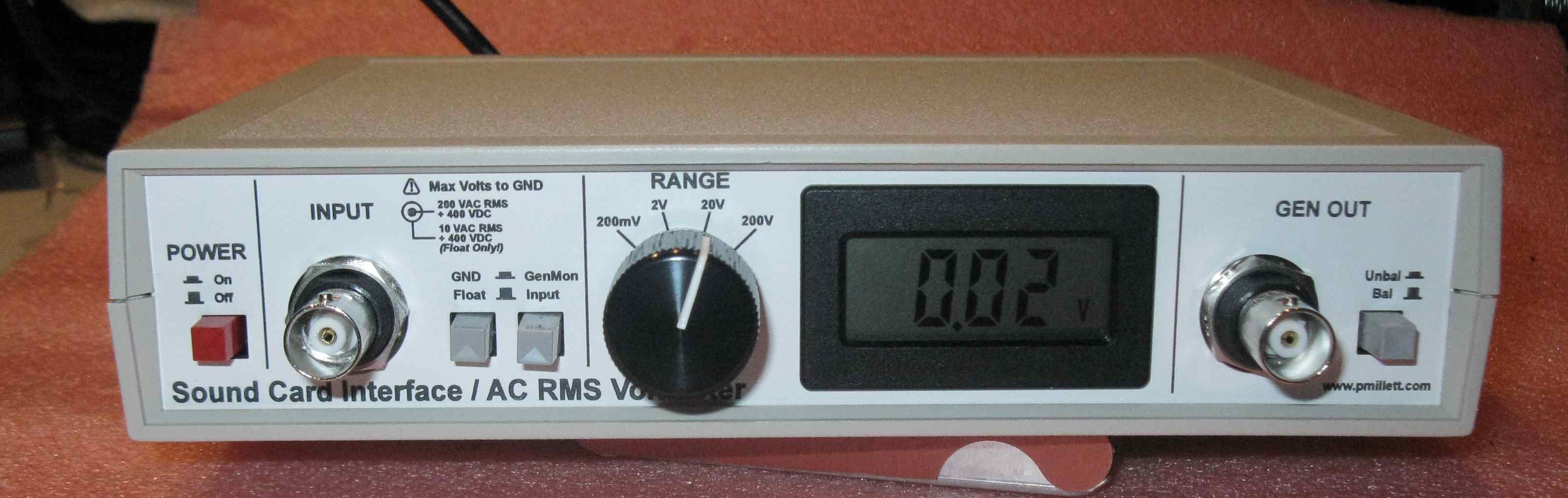
The input is provided on a BNC jack. I chose BNC because it's small and is easy to adapt to whatever you need (RCA, bananas, etc.). The outer conductor of the BNC is not grounded (unless you want it to be, by pressing the "GND" button). The input can also be connected to the "generator" output, to monitor the level of the signal going out of the soundcard.
The front end is a floating single-ended circuit. That means that the circuit is not truly balanced, but is not grounded, and the input is differential. I did this because it's easier to implement than a truly balanced input, and it's how my HP 8903A works, and I've found that to work quite well for what I do. The input is AC-coupled to a 100k switched attenuator, giving 1x, 10x, 100x, and 1000x ratios. Since the digital voltmeter module (DPM) has a full-scale of 199.9 mV, the ranges are labeled 200mV, 2V, 20V, and 200V. The negative side of the input is connected via a 100k resistor to ground to provide a bias current source for the input amplifiers.
One could scale all the input resistors by a factor of 10 and get a 1 megohm input impedance. This might seem desirable as it would allow using 10x or 100x scope probes, which provide very little load to the circuit under test. The problem is that the input noise and offset would also go up (maybe also by a factor of 10), as the input bias current and current noise of the amplifiers will turn into nose and offset voltage. I opted for lower noise and kept the Zin at 100k, like my HP 8903A. By the way, make sure all those input resistors are low-noise metal film types. No carbon resistors here...
Because of the input configuration, the negative side of the input must be with +/-15V of ground (the soundcard ground). Any signal over about 10V RMS will cause the input amp to clip. So the negative side is really intended to be connected to ground at the DUT. You can successfully measure differential signals as long as they are low voltage, though, like a balanced line-level signal. Note however that the input impedance is 100k resistance between the - input and ground, and 100k between the + input and the - input. Not balanced...
Protection is provided by resistors and diode clamps. Both sides of the input can withstand up to 200V RMS referenced to soundcard ground, even if the range is set to 200mV. The input caps block DC up to 400V, again, on both the + and - inputs. So you could, for example, make a measurement referenced to B+ (as long as B+ is under 400V, and has less than ~10V ripple).
The input amplifier consists of a combination of an opamp in differential amplifier configuration and a differential audio line receiver chip. This circuit was chosen to provide high input impedance, decent CMRR, and very low distortion and noise. Note the schematic shows an OPA2604 - I later found the OPA2134 is actually a little better here. Gain of the input amp is set up to deliver 500mV from a full-scale 200mV input.
The output of this circuit feeds the RMS voltmeter (off to the right) as well as a buffer amp that drives the soundcard. A second clipping circuit is placed before the buffer to limit the soundcard output to about 2V RMS. The buffer is a balanced audio driver with a gain of 2 that can drive either balanced or unbalanced sound cards of any input impedance (including 600 ohms) with very low distortion. The output level is 1V RMS max, for a full-scale input.
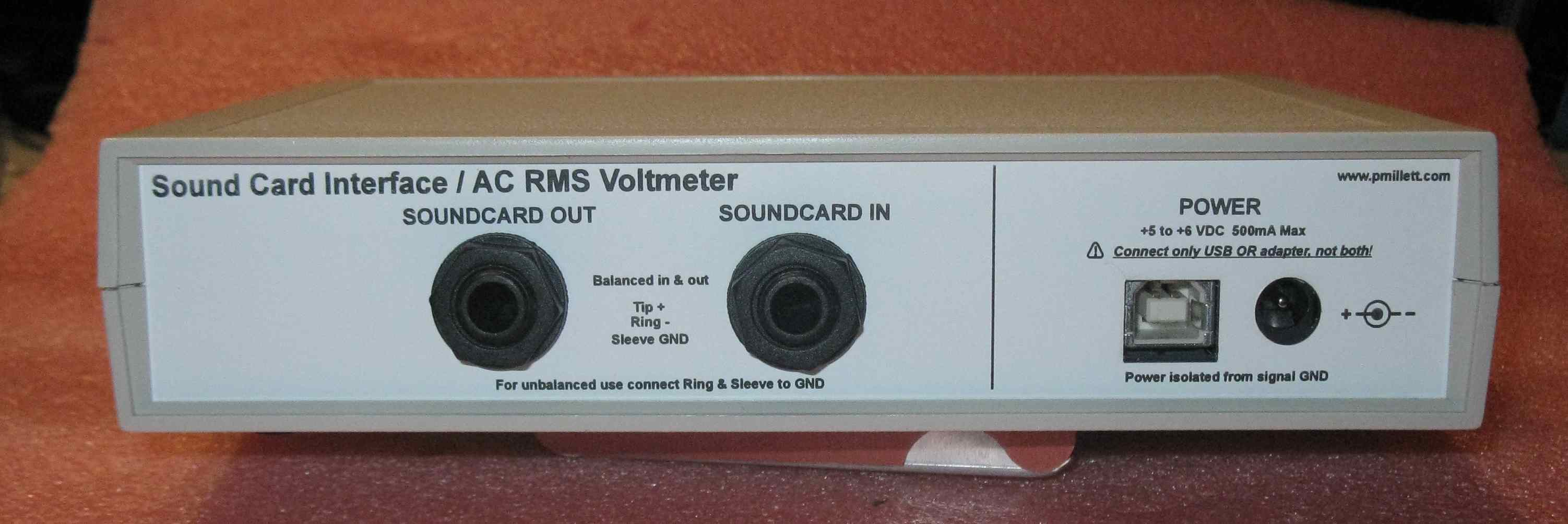
The output (to the soundcard input) is delivered through a 1/4" phone jack, wired in the standard balanced configuration. The logic here was simply that it's what my soundcard uses (an M-Audio Audiophile 192). It is also inexpensive and readily available.
The true RMS voltmeter section takes the signal from the input buffer and feeds it through an Analog Devices AD536 true RMS converter IC. The output is a DC voltage indicative of the true RMS value of the input. This is sent to an off-the-shelf DPM module through a divider that lets you adjust the full-scale meter reading (and through yet another diode protection circuit). A logic circuit is used to control the decimal points and "milli" indicators on the DPM, so the meter shows the correct value based on the range switch setting.
Next is the output buffer amplifier. This circuit uses a differential audio receiver IC to get the signal from the soundcard (again via a 1/4" balanced phone jack), and a buffer that can drive single-ended or differential outputs. On the output connector (a BNC) a switch is provided to ground one side of the output for single-ended operation. The circuit has a gain of 2, so you can get a bit more amplitude out, and drive lower impedance loads, that you can directly from the soundcard.
Lastly, the power supply. One of the problems making measurements with a soundcard inside a PC is that a PC is a very noisy place. Ground loops can cause horrible noise floors. So the power supply for the circuit is an isolated supply, and the only connection to ground is via the soundcard signal ground terminals. I used an isolated DC/DC converter to generate the required bipolar supplies (+/- 15V here) from a single input. Since you already have a giant power supply (the PC), I added a USB connector so you could power the box from a USB port (or optionally from an AC adapter of 5-6V). Since the USB ground is isolated from signal ground, it doesn't introduce any noise.
I designed a PCB to contain this circuitry and fit inside an affordable off-the-shelf plastic box.
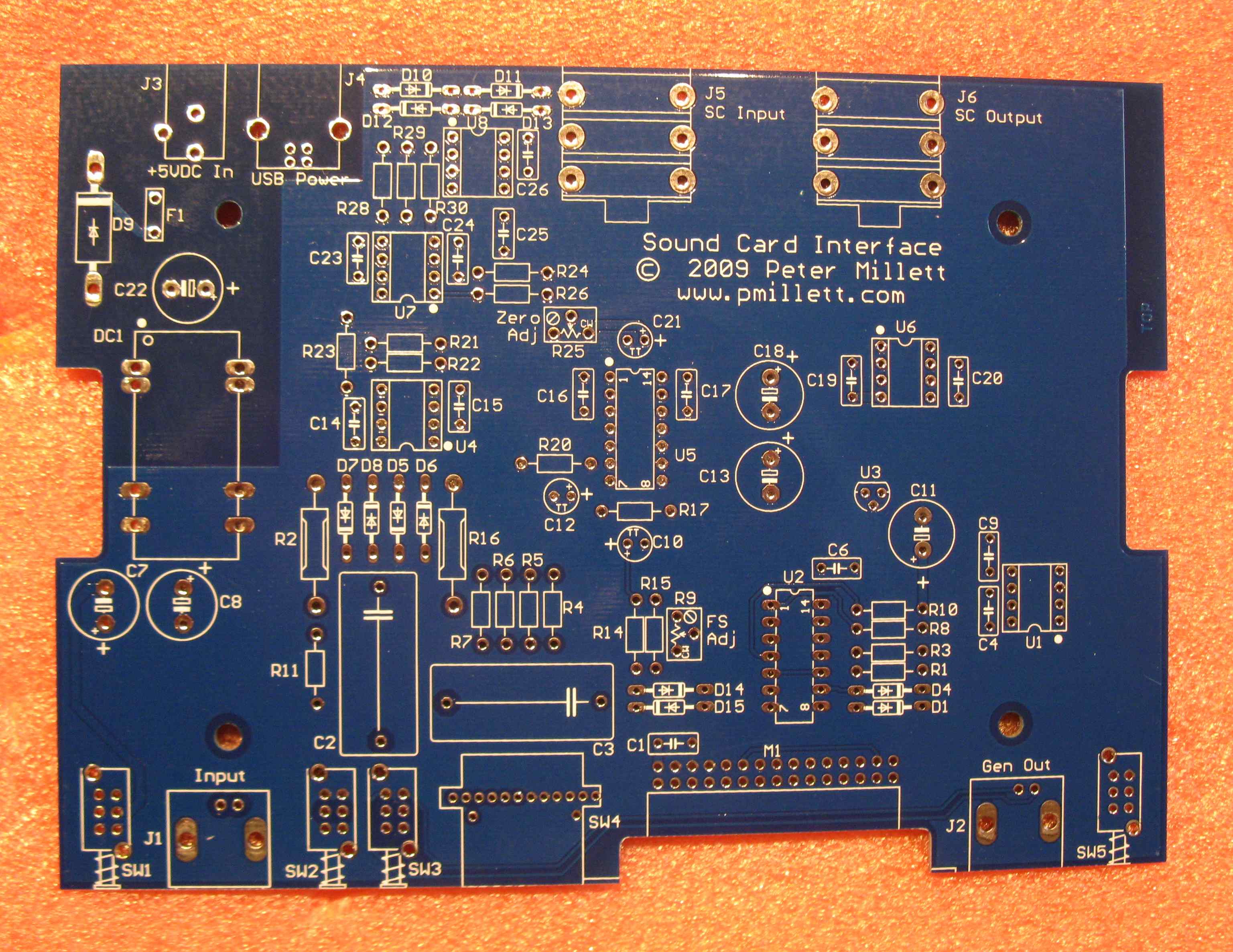
Assembly is as simple as stuffing the parts. All through-hole, no SMT. I used sockets for the audio ICs, though you really don't need to.

The DPM module connected to the PCB through a right-angle socket connector, so it can be installed through the front panel.

The parts should be readily available form the "usual sources", including Mouser, Digi-Key, Newark, Farnell, Allied, etc. The plastic case might be problematic outside the USA - it comes from Bud Industries, a US company. They have limited international distribution. You can always buy from one of the US catalog distis, though shipping can be nasty. Of course, you could always build this into a case of your own choosing.
After you stuff it, you need to make a couple of adjustments to calibrate the meter section. There are two adjustments on the board. One is to zero the DC offset of the input amp - this could probably be left out with no ill effects. Basically you set the range to 200mV, short the input, and turn the pot to get as close to a zero reading on the DPM as you can. You will never quite get to zero, because there is AC noise here as well. Mine "zeros" to 0.3mV.
The other adjustment is a full-scale adjust. If you have a calibrated AC voltmeter, you can set the full-scale adjust to make the DPM match the reading on your meter, with the input signal of your choosing. If you only have a DMM, you can use it - just feed in a 50 or 60Hz signal (filament voltage would work) to both your DMM and the soundcard interface, and adjust the full-scale pot so the reading you get matches your DMM. (Don't try this with any other frequency, or anything but a sine wave, unless you have a really good DMM - most are only accurate on line frequency).
Here is the full BOM in PDF or XLS format. The total cost to build this, including the enclosure, PCB and front/rear panels, is about $170. I am selling the PCB and front/rear panels as a set on eBay - you can find my items for sale by searching for seller "pmillett".
Of course, for this thing to be useful, it has to add very little additional noise and distortion into the signal path, so as to not influence the measurements. Here are some FFT plots and other measurements of the interface... (Plots are hyperlinked so you can see full-size images.)
The first FFT plot shows the M-Audio Audiophile 192 card with the inputs grounded directly at the jack. So this is the noise floor of the soundcard alone.
The next two plots show FFTs of the HP 8903A generator connected directly to the soundcard input. The fist is 200mV, 1kHz - the second 2V RMS - and the third 19kHz at 200mV RMS. You can see harmonics and other artifacts popping up here. The 8903 has a very good generator, so I believe most of this is being generated by the soundcard itself, though some of the 2nd harmonic might be from the generator.

The next FFT shows the soundcard interface connected to the soundcard input, with the interface's input BNC shorted. This is the noise floor of the soundcard plus the interface's input circuitry. You can now see 60Hz and harmonics of 60Hz show up. Interestingly these are present (at somewhat lower levels) even with the power disconnected, so they are being picked up from the environment. I made no attempt to shield the PCB - these measurements were with the board lying on my bench. These components might be reduced with some shielding - I noticed that they drop up to 20dB when I pick the unit up off my bench! Still, over 95dB down. Keep in mind 0.01% THD+N is -80dB...
Now we introduce a signal from the 8903 into the interface's input. First 1kHz at 2V RMS on the 2V range (two plots - the second with the unit picked up off the bench, which lowers the 60Hz component by 20dB), then 200mV on the 200mV range, and finally 200mV on the 200V range. Finally 19kHz, 200mV on the 200mV range. Similar results to connecting the 8903 directly to the sound card. Notice the THD+N in the second plot: less than 0.005%.

Next we look at the soundcard's generator connected directly to the soundcard input (direct loopback), with the output at 0dB FS (full-scale) and at -20dB FS. At 0dB FS there is a lot of nasty high-order harmonics seen, probably because the input is close to clipping at 0dB FS.
Now a loopback function through the interface, using the "gen mon" function which connects the output signal (at the BNC) directly to the input (also at the BNC). First with the generator set to off on the 200mV range, then at 1kHz, 0dB FS, which corresponds to 8.29V RMS out (measured on the 20V range), then -20dB FS (830mV out, measured on the 2V range). You can see some distortion products popping up at 8V RMS out - this is getting close to the maximum capability of the output buffer. Finally at 20kHz, -20dB FS (840mV on the 2V range).

From all this, you can see that the interface does add some artifacts - especially some 60Hz noise - but for the most part they shouldn't be problematic (especially for tube circuit measurements). Keep the scale in mind here - the bottom of these FFT plots is -160dB! The Audio Precision 2700 (touted as "The Highest Performance Audio Analyzer in the World") series is specified at -112dB THD + noise with a 2V input! For those that think in THD+N percentages, -100dB is 0.001%, and -80dB is 0.01%.
One other important spec: CMRR (Common-Mode Rejection Ratio). The input amp is not a true differential implementation - it is a "floating single-ended" circuit. It does, however, provide some common mode rejection.
By connecting both sides of the input together and applying a 1V, 100Hz sine wave to them - referenced to the soundcard ground - I measured 1.7mV, or -35dB of CMRR. Note that this rejection is pretty much independent of the range setting. This is without trying to do anything special to optimize it (like matching resistors on the input amp). I think this is good enough to help remove some of the ground noise you're likely to get making measurements.
The other part of this design is the true-RMS digital voltmeter. I calibrated the meter to match my HP 8903A meter at 1kHz, 2V RMS, on the 2V range. Then I took a bunch of measurements at different voltage, frequency, and waveform types, and measured the error. Keep in mind the 8903 is not perfect, so some of the measurement error may be in the 8903...
| Waveform | Frequency | Applied voltage | Range | Error (%) |
| Sine | 1kHz | 199mV | 200mV | +0.2% |
| Sine | 1kHz | 1.999V | 2V | 0 (reference) |
| Sine | 1kHz | 1.999V | 20V | +2% |
| Sine | 1kHz | 1.999V | 200V | +15% |
| Sine | 1kHz | 104.5V | 200V | +0.9% |
| Sine | 20kHz | 199mV | 200mV | +0.5% |
| Sine | 20kHz | 1.999V | 2V | -0.3% |
| Sine | 20kHz | 1.999V | 20V | +2% |
| Sine | 20kHz | 1.999V | 200V | 0 |
| Sine | 20Hz | 199mV | 200mV | -2% |
| Sine | 20Hz | 1.999V | 2V | -2% |
| Sine | 20Hz | 1.999V | 20V | 0 |
| Sine | 20Hz | 1.999V | 200V | +15% |
| Sine | 20Hz | 104.5V | 200V | +1% |
| Square | 1kHz | 2.85V | 20V | 0 |
| Triangle | 1kHz | 1.618V | 2V | +0.06% |
Most of the measurements were made with low-distortion sine waves at varying voltages and frequencies. I also tried square- and triangle-waves just to make sure the true MS circuit works correctly.
The measurements that are gray are not expected to be very accurate, as they are made on an incorrect (too high) range setting. For example, measuring 1V on a 200V scale will give you a measurement that is not very accurate percentage-wise, due to things like offset errors. They are shown here just so you can see what happens.
If you exclude those, the measurements are within 2%, or within 1% at higher frequency. FYI, 2% is 0.17dB. This is using nothing better the 1% resistors everywhere. Good enough for home audio experiments, me thinks.
Note that the (valid) 20Hz measurements are about 2% low. This is due to the LF rolloff that is occurring at the input capacitors. this could be improved somewhat by using bigger caps, but they get a little physically large. I used 1uF, 400V caps so I could apply up to 400VDC to the input (like connect it directly to the plate of a tube stage). If you value frequency response over DC voltage, you can put a 10uF 100V cap in it's place.