
829B Triode-mode amplifier
I've built a real stereo version of the 829B triode SE amp:
The base is made of Zebrawood, finished with oil - cost me about $50 for the wood but boy, it sure looks nice. The top plate is 0.029" copper sheet on top, with 0.062" PCB material underneath. The layering let me hide all the screws under the top plate, and the PCB material makes it easy to solder to a ground plane.
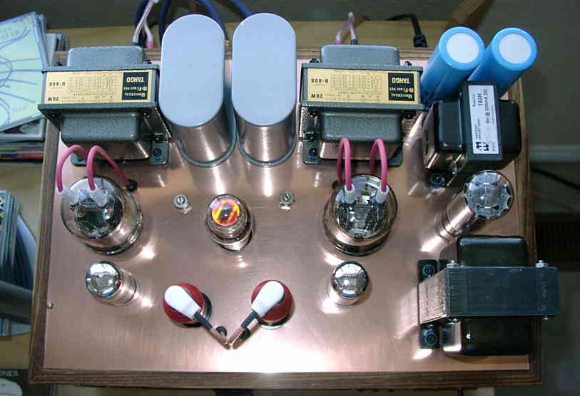
You can see the 829B's in front of the OPT's. In front of them are 7N7's (parallel-connected cathode followers), and in the front are a pair of EF37 pentodes, which are the input stage.
Here's a look at the inside:
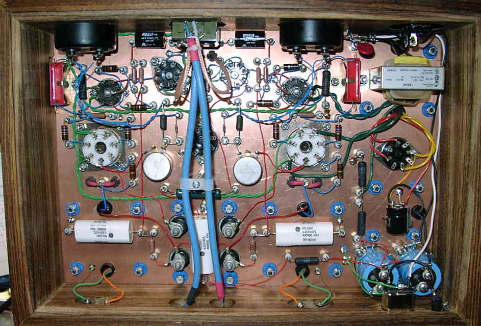
I used a different construction method than I have in the past - I used single-point terminals. I found some Teflon turret terminals at a local electronics joint for $0.30 each (Newark sells them for just over $5.00 each!), so I decided to use them here. You have to drill a lot of holes (about 75 in this amp), but it allows you to put parts exactly where you want them.
I also used the PCB as a ground plane. I'm sold on this method of construction, as opposed to trying to do wired star grounds. This is a lot easier and neater, and works very well.
Here are some more detail pictures (click on the photo for a larger version):
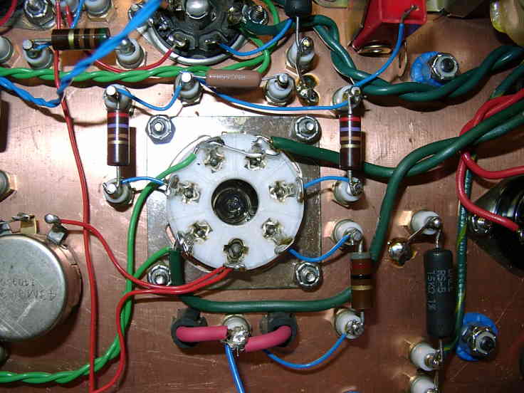

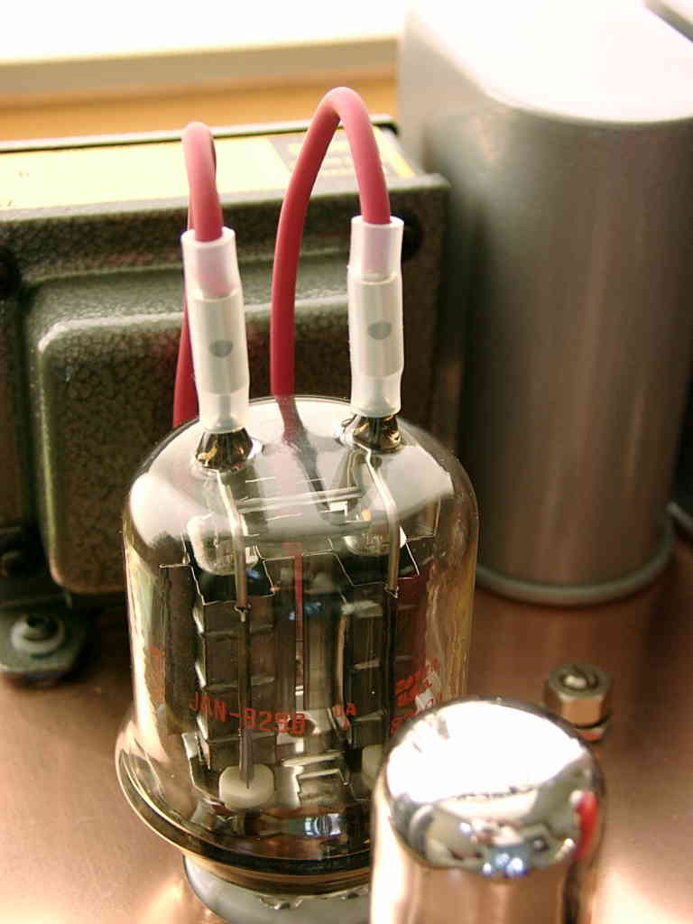
One thing I puzzled over for some time was how to connect to the 829B anode pins. It's hard to find anything that will fit them, and what I could find was uninsulated. I came up with a simple solution: I removed the "guts" from a euro-style terminal block, put set screws in it, and covered it with silicone tubing to insulate it. I also used silicone test lead wire, so the insulation doesn't melt. All in all it worked well, at least at the (relatively) low power dissipation that I'm running. The wires run just cool enough that you can touch them, so I think all is well.
I'm running the 829B's at about 80mA, B+ of 320V, with cathode bias. For details look at the schematic (below). I don't seem to get a lot of difference varying the bias from 60 to 100mA.
The amplifier is -3dB down at 18Hz (by design), and the HF response is excellent - 3dB down at over 70kHz. It clips at about 5 watts. It's incredibly quiet; I measured -70dB referenced to 1 watt, and if I cut off the 60/120Hz, it's more like -80dB!
So how does it sound, you ask? I'm still letting it break in, but so far it's wonderful, better than it has the right to be for so little money (I bought 6 829B's, 4 RCA's and two Mullards, for a total of about what a single Sovtek 2A3 would cost). Very natural sounding.
The bass of this amp really surprised me. It is very clean and strong. Probably partly due to the output transformers, Tango U808's, and the very low impedance power supply (mongo capacitors).
The driver circuit performs very well. It clips at about 50V RMS (+/- 70V). The 829B only needs +/- 22V, so it has plenty of headroom.
Here is the full schematic of the power supply and amplifier, as built (45kB PDF file).
Also, if you're interested in building something like this, I did some AutoCAD work and generated a mechanical drawing (113kB PDF file) and a parts layout (138kB PDF file) (as viewed from the inside). If you have OrCad and/or AutoCAD and would like the source files for any of these, email me at:
![]()
Here is some data I took while the amp was on a breadboard:
Here's a scope shot of the driver output (upper trace) and amp output (lower trace) at 5.3V RMS out into 8 ohms (about 3.5W):
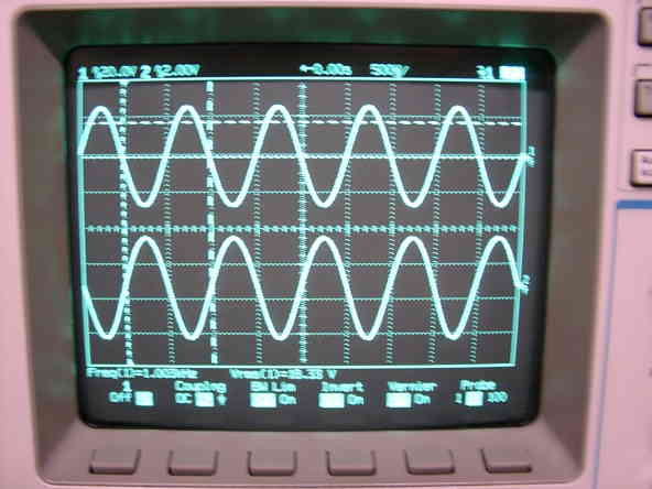
I know it's hard to see, but there is about 4% THD on the output, mostly second harmonic. I hooked up my laptop and ran a spectral analysis, which looked very nice - mostly second harmonic, with progressively lower amounts of the next harmonics. Sorry for the lousy screen shot (with a camera - I need to get a Ethernet card for my laptop!)
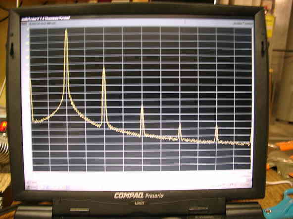
This is not a low-distortion amp; even at 1W out, the THD is almost 1%. But the harmonic profile looks pretty good.