813 Single-ended Triode Amplifiers with microprocessor-controlled power supply
(Most images are hyperlinked to full-size JPG's, just click on the pictures)
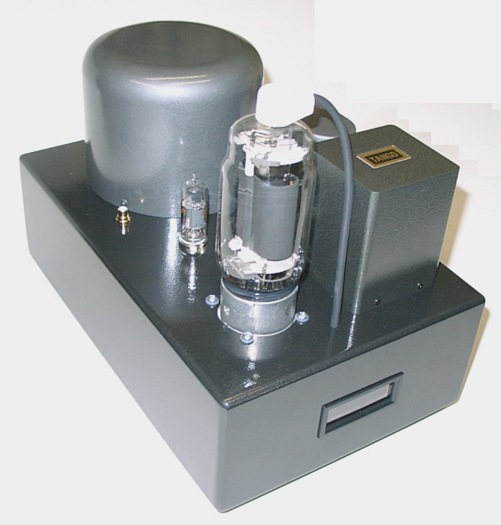
Before...
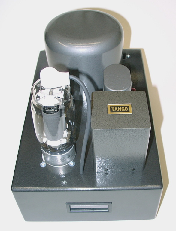
And after...

This is a single-ended triode amp that I built using the 813 transmitting pentode, connected as a triode. It's a fairly powerful SE amp that works very well. It uses a single pentode as the driver (a 12HG7 video amp tube), and a solid-state power supply with a microprocessor controller.
DANGER! HIGH VOLTAGE!
This amp generates around 1000 volts, and the power supply described below can deliver a lot of current. The result is that there is a real hazard from the voltage and energy available. DO NOT TRY AND BUILD ANYTHING LIKE THIS UNLESS YOU ARE COMFORTABLE WITH HIGH VOLTAGES, AND ARE FAMILIAR WITH THE RISKS! Don't come looking for me if you start a fire or electrocute the cat! When working on high voltages, keep one hand in your pocket, and NEVER LEAVE ANYTHING TURNED ON UNATTENDED! You've been warned...
The amp
Here's a schematic of the amplifier. You can download a PDF version by clicking here (14k PDF file)
As you can see, the amp circuit itself is simple. I made up for this simplicity in the power supply, as you'll see further down the page!
The driver
The main peculiarity of the amp circuit, I guess, is the single-tube pentode driver. I experimented quite a bit with the 12HG7 and 12GN7A tubes, both of which are high Gm pentodes designed as video output amplifiers for color TV's. They are amazing devices, capable of providing very low distortion, high gain, and low output impedance all at the same time... much better than you can get with any single triode I've seen.
Here is some performance measurements I took of the driver stage, by itself:
Conditions:
B+ = 400V
Vg2 = 150V (regulated)
Plate load = 4000 ohms
Cathode resistor = 50 ohms, unbypassed
| GE 12GN7A | RCA 12HG7 |
| 5% THD @ 89V RMS (1kHz), 2nd + 3rd + ... harmonics | 5% THD @ 100V RMS (1kHz), 2nd + 3rd + ... harmonics |
| 1.8% THD @ 50V RMS (1kHz), 2nd + 3rd | 1.2% THD @ 50V RMS (1kHz), 2nd + 3rd |
| 0.3% THD @ 10V RMS (1kHz), all 2nd harmonic | 0.26% THD @ 10V RMS (1kHz), all 2nd harmonic |
| 0.12% THD @ 5V RMS (1kHz), all 2nd harmonic | 0.12% THD @ 5V RMS (1kHz), all 2nd harmonic |
| Ip = 34.2mA | Ip = 34.4mA |
| Ig2 = 5.8mA | Ig2 = 5.6mA |
| Vp = 250V | Vp = 250V |
| Wp = 8.5W | Wp = 8.6W |
| Wg2 = 0.87W | Wg2 = 0.84W |
| A = 38 | A = 40 |
| -0.23dB @ 20kHz, -2dB @ 100kHz into 100k | -0.18dB @ 20kHz, -2dB @ 100kHz into 100k |
| -0.68dB @ 20kHz, -6dB @ 100kHz into 100k + 470pF | -0.68dB @ 20kHz, -6dB @ 200kHz into 100k + 470pF |
The driver has a very nice harmonic profile, with the 3rd harmonic always below the 2nd. At lower levels, the 2nd is about the only harmonic that's measurable. For some reason pentodes seem to have the reputation for creating more high-order harmonics, but it's simply not true in a single-ended design. This driver tests, and sounds, better than any of the possible two-triode drivers I tried, like 6SN7 direct-coupled, or 6SL7 SRPP. It also does much better than a 6C45pi-E.
I also tried these tubes triode connected with a CCS, and they did well that way - about the same as a 6C45pi did, I guess. But I preferred the pentode connection. Try it, you'll like it!
The output stage
The output stage is an 813 tube, connected as a triode. The 813 is a ~100W pentode designed for radio transmitter and modulator service, and was used in the WWII timeframe, I think. It was a common tube in smaller AM broadcast transmitters, especially as a modulator.
I got much encouragement, as well as triode curves for the 813, from Paul LeClercq. He has posted info on the 813 triode push-pull amps that he's built, as well as the triode mode curves for the 813. By the way, the grid lines on the curves are at 10V increments; the first (leftmost) is 0V, the next -10V, then -20V, -30V, etc.
I operate the output stage with a plate voltage of about 850-900V, and a plate current of 100mA. I used fixed bias, which requires around -75V. The OPT is a Tango XE-20S, connected as 5k : 8 ohms. I suspect 5k is probably about the lowest load you'd want to use with the 813.
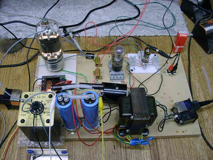
Here are some measurements I made of the amp. Note that these were on the breadboard, not the final product:
Conditions:
RCA 12HG7 driver as described above
Vp = 800V
Ip = 100mA
Vg1 = -75V
Zl = 5000 ohms (Tango XE-20S 5000:8)
Distortion:
5% THD @ 12.6V RMS into 8 ohms (20 watts), with 1.6V RMS input, at 1 kHz
1.1% THD (-39dB) @ 9V RMS into 8 ohms (10W)... 2nd harmonic -46dB, 3rd -41dB, 4th -48dB*
0.18% THD (-55dB) @ 2.77V RMS into 8 ohms (1W)... 2nd harmonic -40dB, 3rd -55dB (in noise?), 4th -49dB*
*note that I'm not sure that the absolute numbers for the harmonics are right, but they are relative to each other
Low frequency performance (OPT limited):
5% THD @ 20Hz: 3.4V RMS (1.5W)
...@30Hz: 5.3V RMS (3.5W)
...@40Hz: 7V RMS (6.1W)
...@50Hz: 9V RMS (10W)
...@60Hz: 10V RMS (12W)
The power supply
The power supply I built for the 813 amp is a solid-state rectified supply that uses two large toroidal transformers, one for the high voltages, and one for the low voltages (filament power, etc.) It uses a microcontroller to sequence voltages at power-up, and monitor power supply voltages and plate current, as well as temperature. Data is displayed on an LCD display, and if any parameter goes out of tolerance the amp is shut down and an error message is displayed.
Power supply schematic (619k PDF file)
The HV supply uses Plitron 067053201 225VA toroidal transformer, which has two 175V windings that are connected in series to get 350 VAC. A voltage doubler is used, which produces around 1000 volts, and at the midpoint of the doubler capacitors, about 500V. These voltages are filtered with RC filters to get the 813 B+ of about 850-900V and the driver B+ of around 400V. The driver G2 supply of 150V is derived from the 400V supply with a zener regulator.
My original HV supply design was to use linear regulation. I never got the regulators to work to my satisfaction, and after blowing up a handful of power FET's, gave it up in favor of a simple RC filter. Chokes would be better than resistors, but at this point I was pretty committed to the mechanical design, and didn't have any room for them.
The HV supply is controlled by the micro with a relay in the primary of the HV transformer.
The low-voltage supplies all run from a large 36V AC source, a Plitron 067018201 225VA toroidal transformer. This is rectified to give approximately 50V DC. This 50V DC rail is converted to +12V by a buck regulator on the power supply board, and to 10V for the 813 filament by a pair of isolated 5V DC-DC converters ("quarter-bricks", used in telecom equipment).
The 12V supply is used for the driver filament, as well as powering miscellaneous stuff like relay coils. It's also used to power linear regulators to generate 5V and 3.3V for the controller and LCD display.
The 10V filament supply passes through a polarity reversal relay, which is energized every other time the amp is powered up (the micro remembers the last state in flash memory) to reverse the polarity of the DC filament voltage. This theoretically keeps one side of the filament from wearing out before the other, since the low voltage end of the filament should tend to emit more electrons than the high voltage end. The 10V filament supply is DC isolated from the input (floating), and plate current is measured by placing a small sense resistor in the path to ground. Power to the filaments is filtered by a toroidal common-mode choke, which makes the filament circuit pretty high impedance to anything over around 1000 Hz, and also serves to reduce any remaining noise form the switching DC-DC converter.
The 36V AC is also applied to a small transformer working "in reverse" (secondary as primary, etc.) to generate the bias voltage. The bias is zener regulated, and I notice no more than a few mA of variation in the plate current, even with 10% changes in plate voltage. Note the arrangement of resistors around the bias pot, which provides full bias to the tube if the pot happens to get dirty and open - gotta think about this kind of thing when you're talking about a design that can easily pump a few hundred watts into the tube before the OPT winding opens!
The microcontroller
In order to provide sequencing of the power supply, monitoring of critical voltages, currents, and temperature, and provide a display of these things, I used a microcontroller. I used a Cygnal (now Silicon Labs) C8051F206 processor, which contains, among a lot of other things, built-in flash memory and a 12-bit A/D converter with a whole bunch of inputs. This is really a single-chip data acquisition system, a very nice device.
B+ voltage, bias voltage, plate current, temperature, G2 voltage, and the raw 50V DC supply are all measured by the A/D converter in very rapid succession. If any of these items fall outside of the limits programmed into the microcontroller, the amp will shut down, and an error message will be displayed. Error conditions include B+ high or low, plate current high or low, G2 low, bias low, AC line low (determined by measuring the 50V supply), and temperature inside the chassis too high.
The micro also provides a specific power-up and power-down sequence. To power up, the filaments are heated for 30 seconds, with polarity reversed every other power-up as described above. Before B+ is supplied, the bias voltage is checked. As B+ is enabled, plate current is measured to ensure a quick shutdown if the maximum value programmed is exceeded. Then, the normal monitoring loop is entered, and plate voltage and current is displayed on the LCD, alternated with the temperature inside the case.
The micro displays info on a 1x16 line LCD character module. Here are some pictures of typical displays:
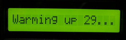
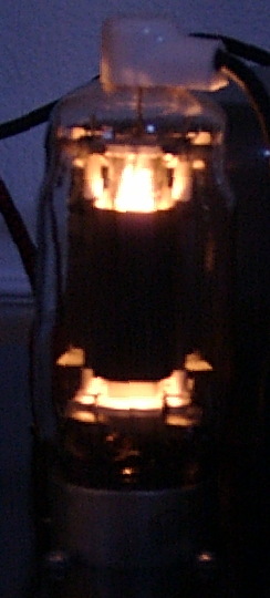
Warming the filaments
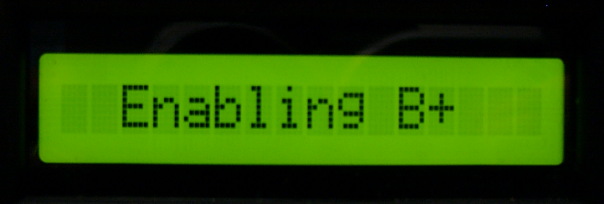
Turning on B+
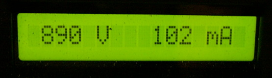
Normal plate voltage/current display
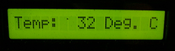
Temperature display
If you're interested in such things, here's the assembly-language code that runs in the amp. This is 8051 code written specifically for the Cygnal C8051F206, so it won't work exactly on other processors, but if you know 8051's it's not hard to port.
Source and oblect code and listing (37k ZIP file)
If you'd like to tinker with this sort of thing (I highly recommend you do it) you can get a development kit from Digi-Key or directly from Silicon Labs that includes a demo board, and all the hardware and software you need (except a PC) to write code, and download it to your target board, all for $99! Not that long ago (OK, so maybe it was 1984 or so) I paid over $10,000 for a system with the same functionality. Amazing.
I wired an LCD display onto the demo board, and used a bunch of pots to simulate the voltages, and developed the code on the demo board. Then you just use the serial JTAG adapter that comes with the demo board to program the flash EEPROM in your own board. You could even use the demo board itself as a controller if you wanted to, for $99 it's a viable way to go.
Construction details
The power supply for the amps are constructed on a PC board. The audio section, like my 829B amps, is built point-to-point using single-point terminals on bare copper-clad PCB material.
I built the amp chassis out of MDF. I would not encourage you to do this, though - the MDF traps too much heat. I started off by trying small fans to move air through the box, but it was too noisy. I finally went with a perforated bottom, and added air holes along the sides of the box. Even so, it gets hotter inside than I'd like. In fact, that's why I added the temperature sensor to the micro, to be able to shut down if it gets too hot in there.
You can download an AutoCAD DXF file of the amp layout (WARNING, BIG 1.52MB DXF file) if you have AutoCAD or a CAD program that can read DXF files. This file shows most of the interior wiring, as well as all the parts. It is not dimensioned, but is drawn to scale.

This view shows the inside of the chassis, with the bottom hinged open. The copper clad PCB with the parts on it is mounted on the chassis underside, held in by the tube socket screws, and the PS PCB is mounted to the bottom of the case. You can see the LCD display at the left hand side of the picture; it plugs into the PS PCB.
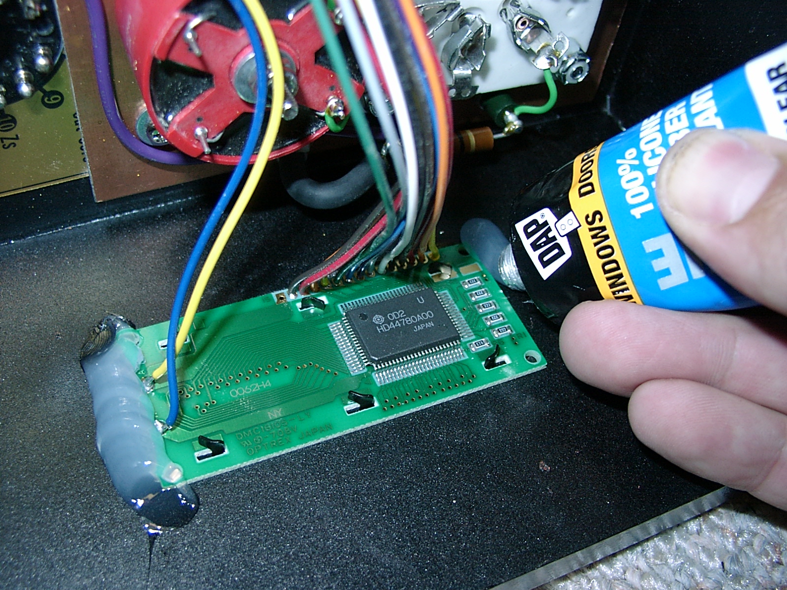
The LCD display is glued into a cutout on the front of the box with RTV. Wires run off to the PS PCB.
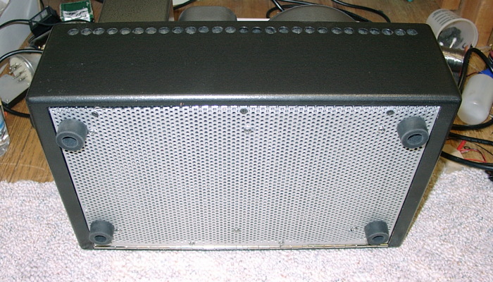
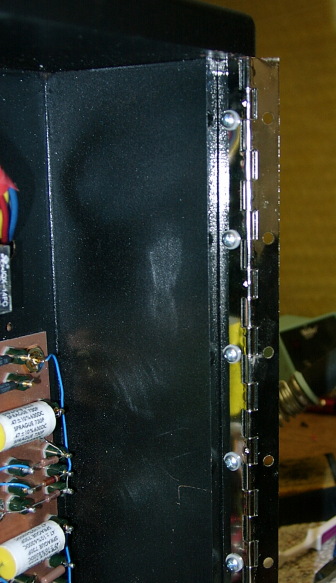
The bottom of the case, made out of perforated aluminum, is attached to the box with a section of continuous hinge (piano hinge).
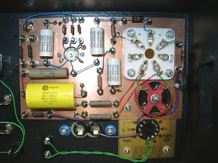
A view showing the interior wiring, pretty self-explanatory. The fat purple wire is rated for 5kV. The anode lead comes in at the right edge of the picture (it's black and hard to see). The two power resistors going from the filament pins to ground provide the primary signal current path from the cathode to ground.
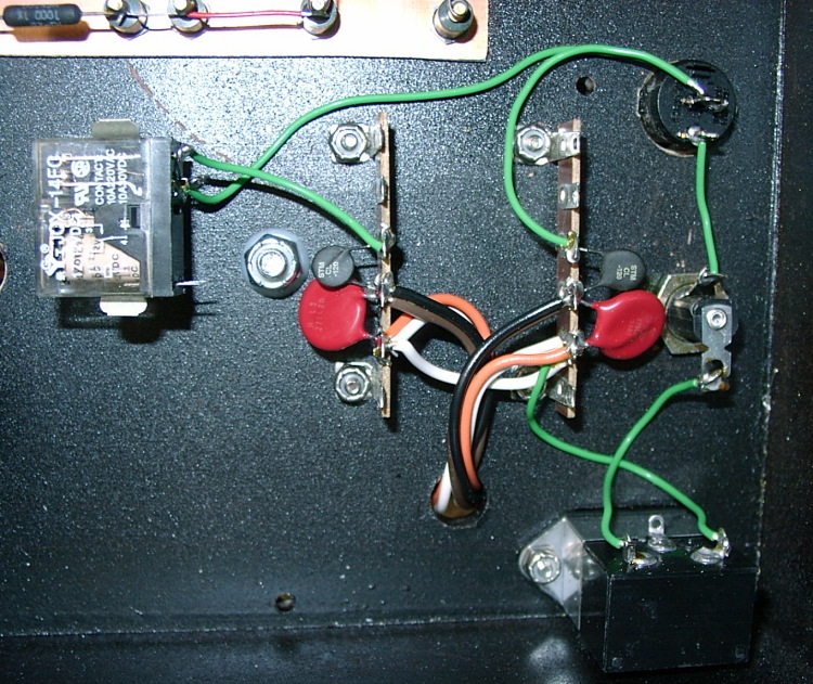
The AC wiring, showing the relay that controls the primary of the HV transformer (coil isn't wired yet). You can see MOV's (metal oxide varistors, the red discs) and inrush limiters (the black discs) were used on each transformer primary.
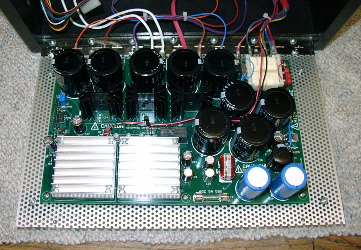
A view looking down onto the PS PCB. The squares with finned heatsinks are the 5V quarter-brick DC-DC converters, wired in series to supply the 813 filament. The black heatsinks are used with TO-220 power resistors (part of the RC filtering). The small transformer in the upper right is for the bias supply.

The bare PCB material with single-point terminals before installation and wiring. The big hole is for the 813 socket, the small one for the 12HG7 socket, which are mounted to the chassis after the terminal board (actually, the screws hold the terminal board in). Note the common mode choke installed in the board before assembly (to hide the screw head).
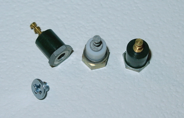
Some assorted single-point terminals. These are attached to the PCB material with flat-head screws, countersunk flush into the PCB material.

This is what's under the aluminum can: two Plitron toroidal transformers. The low voltage one is part number 067018201, 35+35V at 225VA (windings connected in parallel), and the high voltage one is 067053201, 175+175V 225VA (windings connected in series). In case you're wondering if it's OK to stack two toroids this way, I cleared it with the Plitron engineer - he told me that there are no magnetic issues, the only thing to worry about is heat buildup. This design is so conservative that the transformers don't even get warm to the touch, so we're OK here.
So, you wanna build an 813 SE amp... some words of wisdom?
As in all projects, I learned a few things building this amp that I should share with any potential builders out there.
First of all, be VERY careful with a high-voltage, low-impedance power supply like this. Subtle things can bite you. For example, if you look at the schematic you'll see some resistors in series with the HV secondary coming onto the PS board. These serve to help filter rectifier noise from getting out to the transformer. and also provide peak current limiting for the SS rectifiers. Now, they only dissipate something like 1/4 watt RMS... but the instantaneous peak power dissipated there is quite large. I initially had metal film resistors in series-parallel there, plenty of margin for the RMS power. But on about the third power-up cycle, I heard a most impressive sound as the metal film vaporized and created a nice plasma arc that persisted for a second or two. Moral of the story: you MUST use a resistor like a carbon composition in an application where there are large peak powers to be dissipated. Metal film doesn't work.
You'll also notice lots of resistors stacked in series in several spots. This is because when you're talking about 1000V or so, you have to worry about the voltage ratings of resistors, not just the power. A 1206 chip resistor will probably vaporize with 1kV across it, even if it's several megohms.
You even have to think about the wire. Normal wire is rated for 600V. I'm sure you could get away with running it at 1kV, but I went out and got some 1.5kV wire. I used 20kV test lead wire for the anode connection, since it is exposed on the outside of the amp.
It is probably easier and safer to build a conventional tube-rectified HV power supply than the one I built. Tube rectification is much more forgiving, and acts as a current limiter, so peak currents and their associated noise isn't as much of a problem. LC filters also allow you to use smaller capacitors, which pose less of an energy hazard than the large electrolytics I used; you can deliver a lot of energy from hundreds of uF of caps charged to 900V.
You could still use a solid-state LV supply and microcontroller circuit with a tube HV supply. This is what I'd do if I were doing it over again.
Also, use a metal chassis to help keep the inside cool. This would be less of an issue with an LC-filtered supply, but there's still a large heat load created by the 50W filament power supply.